Showing posts with label qrp2004 build. Show all posts

Thursday, January 17, 2013

QRP2004 Control Board - ExpressPCB Version


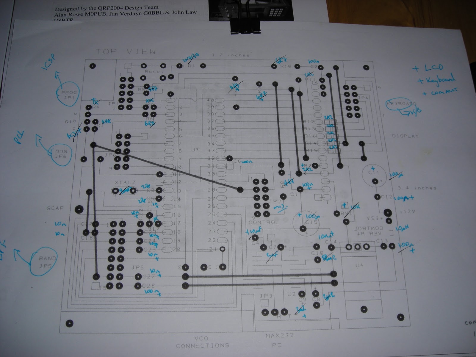
I was asked if an electronic version of the PCB masks exist for the project. They don't and as I like using it I have started to create Express PCB versions of the PCB. This is the control board. Note I have used the NARROW SOIC-16 version of the MAX232/ST232 SMD I will also consider the normal DIL version too.

The layout are sized exactly the same as the originals and generally will follow the original layouts, right now no bottom layer tracks exist on this image on the blog.

I'll work through all the boards and possibly build up an alternative making a few additions, I may produce a layout using SMD components where possible for many of the discrete components especially the R and C.

Note I do not create the .sch files just the .pcb files.

I'll wait to hear from the project group if they mind these being shared.

Same as above in poor French:
Le même que ci-dessus en français pauvres. Apologie de langue maternelle française.


On m'a demandé si une version électronique des masques PCB existent pour le projet. Ils ne sont pas et que je veux l'utiliser, j'ai commencé à créer des versions Express PCB de la carte. C'est le tableau de commande. Remarque, j'ai utilisé le ETROIT SOIC-16 version de la MAX232/ST232 SMD Je vais également examiner la version DIL normal aussi.
La mise en page sont exactement les mêmes dimensions que les originaux et en général suivront la mise en page originale, à l'heure actuelle aucune piste couche de fond existent sur cette image sur le blog.
Je vais travailler par tous les conseils et peut-être constituer une alternative faire quelques ajouts, je peux réaliser une maquette en utilisant des composants SMD, si possible pour de nombreux composants discrets en particulier la R et C.
Note Je ne crée pas les fichiers sch. Seulement les fichiers de pcb..
Je vais attendre d'entendre le groupe de projet si elles l'esprit ces partagé.
read more "QRP2004 Control Board - ExpressPCB Version"

Wednesday, January 16, 2013

QRP2004 Control Board - Day 2


The prepared Control PCB is fitted with all the IDC sockets and wire links including all the wire links through the board so the ground plane is connected both sides. In the above photograph you can see I have prepaced some of the components before continuing. On the reverse side there are just two wire links, 5 2K2 SMD resisors and the ST232 SOP SMD IC. Note if you are going to use the project group PCB masks you need to use the ST232CWR WIDE body version.

 
I am building from one of the component sets I previously put together, I printed off a copy of the yahoo group spreadsheet to mark off the components. I have a number of bags that I have presorted the components into according to the boards.

The LCD connections to the Control Board I have used a SIL connection  strip and it is connected to the LCD by a length of ribbon cable. The 7805 regulator will need mounting hardware as well.

read more "QRP2004 Control Board - Day 2"

Saturday, January 5, 2013

QRP2004 Build


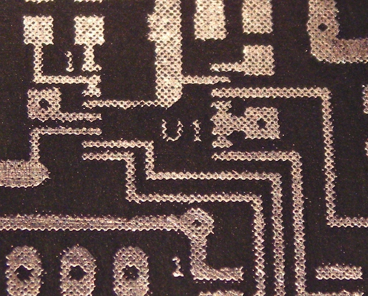
PLL photos with the tiny AD9835 tracks.

Note the laser was on draft 300dpi hence the slight dotty nature of the tracks I have done this as I wanted to test out the process.

Tinning will cover these. This was after just 15 minutes in tin solution.


Just to see how low you can go...this is what you get at 150 dpi printing:


I might b tempted to chase a blob of solder about these pads/tracks
read more "QRP2004 Build"

QRP2004 Build day 1 PHOTOS

Series of photos as the boards are made up.
First clean all the boards
Then iron on the film (audio board as example)
The peel off the film (control board as example)
All the boards then same again bit touched up.
As they come out of the etch, note I use red electrical tape on the reverse
ground plane.
The resist layer cleaned off.
Pair of boards about to be etched
A simple Sodium Persulphate etch bath (note the blue colour is from the copper
in solution)


read more "QRP2004 Build day 1 PHOTOS"

Monday, December 31, 2012

QRP2004 Build day 1

Here starts the log for the build today easy first day.

I'm creating the PCB and my process is to use press and peel film (Maplin AB15R) so I use the REVERSED images of the CU layer you can obtain either from the qrp2004 project team website (http://myweb.tiscali.co.uk/qrp2004/) or the yahoo group (http://groups.yahoo.com/group/qrp2004/files/) Printer is a laser doesn't work with an inkjet printer, Samsung ML-2240 and I am printing 1200x1200 dpi and as DARK as I can get it.
Make sure you check the print size is right. I used a 40pin DIL socket and couple 8 pin DIL sockets to check the sizes. Mine I had to print at 107% size. Print to normal paper until you get the size right.

Anyway I have 7 nice pieces of blue film ready to use.

It is still cold out so doing the rest of this in doors.... (except the etching)

1. Cut out 7 pieces of PCB sized to fit. Mine are slightly oversized.
2. Clean them of all grease and finger prints (I use Acetone and then fine wire wool and emery paper in a circular pattern). You end up with 7 shinny pieces of PCB. Now clean all the wire wool or emery paper remnants away
3. Iron on or feed the sheets and PCB through a laminator (I will be testing the later option on another build).
4. Allow to cool, peel off the film.
5. I use black marker (permanent) on the top ground plane side, you can use close fitting tape etc... your choice.

Outside now in shack...

6. Etch. You do not need a tank but I home-brewed one from a fish tank heater and aerator pump. I use either Ferric Chloride or some clear etchant. The home-brew tank I set the solution to 35degrees C and let it bubble away for about 35 mins and the boards are usually fine. Wash the boards with water and allow to dry.
7. You have a choice: either remove the etch resist pattern off the boards now or wait until after drilling the boards. I will tin mine (you do not need to) so will remove the etch resist and the tape or pen from the other side and I use a dip solution, you can tin too by chasing a bead of solder around the board (hint this is much easier when NOT drilled!). If not tinning and if you remove the resist the copper will tarnish quickly so you might want to use a flux spray like KS10.

Now the boring bit... drilling c900 holes! This might take a while.
I use a Dremel in a stand (the task is hopeless if not in a stand) with 0.7mm drill bit. Note some holes will need to be enlarged will cover those in later posts.
Drill all the 3mm holes for the mounting and the other 4-5mm holes for the TO220 and other transistors.

I think the drilling holes is why so many home-brewers have moved over to SMD...

I'll post some photos later.

You can use a photo resist and print the CU layer images to sheets and expose and develop etc... but I have not done it that way but many other homebrewers do.
read more "QRP2004 Build day 1"

Thursday, December 13, 2012

QRP2004 Build


I have had a few questions about this project ( http://groups.yahoo.com/group/qrp2004/ for details) so I will start a build from scratch and blog it here starting in the new year (i.e. 2011).


This is the designed polyphase network for the QRP2004

Copyright © 2004 - 2005 by QRP2004 Design Team

The project design team include details of the design and method where you can look at options using different components (depending on what you have to hand), using different components the results are:
(RED) C=33nF, R (Kohm) 12,10,6.8,3.9,2.7,1.8,1
(BLUE) C=10nF R (Kohm) 47,33,22,15,10,6.8,5.6


See the project docs for details.

QRP2004 Web Site: http://myweb.tiscali.co.uk/qrp2004/
read more "QRP2004 Build"