Hi all,
This is a post to compliment my post on modding the EEE PC to do awesome things.
I will describe, in detail, the steps required to strip your eee pc 701 down to its bare bones (you have to figure out how to put it back together again yourself).
 1 - Remove battery, modem bung, RAM door
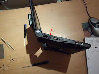
Removing the battery is easy. Grap the two slidey locks, push outwards, and pull out the battery. The modem bung is nearly as easy, get a fine screwdriver and carefully pry it out of the connector. Finally unscrew the two screws on the RAM door, save these and remove the door.
2 - Remove the keyboard
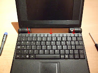
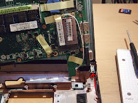
Turn the laptop over, so it is now face up. There are 3 tiny catches at the rear of the laptop, behind the F1, F6 and Break keys. Take a straight screwdriver and push these backwards (towards the monitor), and the keyboard will lift up at the back. Now unclip the ribbon connectors for the keyboard and the mouse (shown below).Lift away the keyboard and keep it somewhere safe.
3 - Removing the outer case Under the keyboard are 9 screws. Remove these with a star screwdriver and save them somewhere safe. Turn the laptop over and unscrew 6 screws from the base.
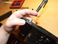 When removing the upper case you should note that the audio connectors are surrounded by plastic which is part of the case you are removing. You should put a straight screwdriver behind this and pry it out gently before removing the top completely
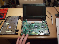 Remove the case evenly upwards (try not to lift the front first as the rear parts will catch on the monitor). Part of the metal will be stuck to two of the chips underneath by thermal stickers. Be careful to pry these slowly so as not to damage or unseat the chips.
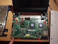
4 - Removing the motherboard
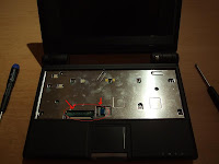
There are two plastic clips holding the front of the motherboard in, unclip these with a straight screwdriver. You need to remove (in no specific order):
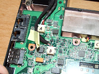
(The third picture above is provided for when you forget which way round the speaker/webcam connectors go)
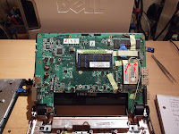
You should now be able to lift the motherboard out. Place this somewhere SAFE - you kind of need this to run your laptop.
 5 - Removing and dismantling the screen
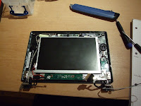
The screen is held to the base by two screws at the base of the screen.
To remove the front bezel of the screen, there are 6 screws. These are hidden under the 4 rubber "feet" at the top of the screen, and 2 hidden under round plastic bits at the bottom. You need to pry these out with a sharp knife and keep them safe. They can be re-attached later with some superglue, though not for a while becuase they will be harder to remove again.
There are small plastic clips around the perimeter of the bezel, which are unclipped by applying gentle pressure. There are also two clips on the inner perimeter (next to the screen, just below the speakers). These can be best accessed by poking a screwdriver from the outside of the bezel, past the speaker and unclipping them.
6 - Congratulations
You have stripped down your EEE PC about as far as you'll ever need to make some mods. I will not provide any more details here. I can be reached by email if you for some reason value my less-than-useful opinions.
This is a post to compliment my post on modding the EEE PC to do awesome things.
I will describe, in detail, the steps required to strip your eee pc 701 down to its bare bones (you have to figure out how to put it back together again yourself).
 1 - Remove battery, modem bung, RAM door
Removing the battery is easy. Grap the two slidey locks, push outwards, and pull out the battery. The modem bung is nearly as easy, get a fine screwdriver and carefully pry it out of the connector. Finally unscrew the two screws on the RAM door, save these and remove the door.
2 - Remove the keyboard
Turn the laptop over, so it is now face up. There are 3 tiny catches at the rear of the laptop, behind the F1, F6 and Break keys. Take a straight screwdriver and push these backwards (towards the monitor), and the keyboard will lift up at the back. Now unclip the ribbon connectors for the keyboard and the mouse (shown below).Lift away the keyboard and keep it somewhere safe.


3 - Removing the outer case Under the keyboard are 9 screws. Remove these with a star screwdriver and save them somewhere safe. Turn the laptop over and unscrew 6 screws from the base.
Note: To keep tiny parts safe I use small boxes, especially for screws. This, combined with counting the number of screws to be removed or re-inserted, virtually eliminates the "parts left over" effect.
 When removing the upper case you should note that the audio connectors are surrounded by plastic which is part of the case you are removing. You should put a straight screwdriver behind this and pry it out gently before removing the top completely
 Remove the case evenly upwards (try not to lift the front first as the rear parts will catch on the monitor). Part of the metal will be stuck to two of the chips underneath by thermal stickers. Be careful to pry these slowly so as not to damage or unseat the chips.
4 - Removing the motherboard
There are two plastic clips holding the front of the motherboard in, unclip these with a straight screwdriver. You need to remove (in no specific order):
- Speakers connector (top left)
- Webcam connector (top left)
- Fan connetor (top left)
- VGA connector (top right)
- WIFI antenna connectors (x2) (underside, top right)


(The third picture above is provided for when you forget which way round the speaker/webcam connectors go)
You should now be able to lift the motherboard out. Place this somewhere SAFE - you kind of need this to run your laptop.
 5 - Removing and dismantling the screen
The screen is held to the base by two screws at the base of the screen.
To remove the front bezel of the screen, there are 6 screws. These are hidden under the 4 rubber "feet" at the top of the screen, and 2 hidden under round plastic bits at the bottom. You need to pry these out with a sharp knife and keep them safe. They can be re-attached later with some superglue, though not for a while becuase they will be harder to remove again.
There are small plastic clips around the perimeter of the bezel, which are unclipped by applying gentle pressure. There are also two clips on the inner perimeter (next to the screen, just below the speakers). These can be best accessed by poking a screwdriver from the outside of the bezel, past the speaker and unclipping them.

6 - Congratulations
You have stripped down your EEE PC about as far as you'll ever need to make some mods. I will not provide any more details here. I can be reached by email if you for some reason value my less-than-useful opinions.


