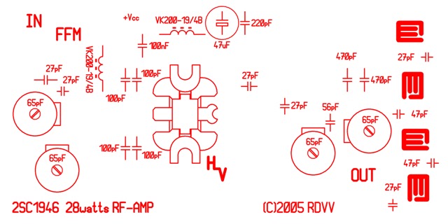
2SC1946 28 Watts FM-broadcast (87,5-108MHz) rf-amplifier
All component values are drawn on the .comp and .silklayer bitmaps, with the following
exception(s);
1.- all four (4) coils (in the lowpass filter section) are:
3.5 turns, 8 mm DIA., 1.2 mm CuL closewound i.e. no wirespacing.
Notes
CuL = magnetwire, enameled copper wire, insulated (rigid) copper wire e.t.c..
(Note: 2 mm equals approx. to #12 A.W.G
1 mm equals approx. to #18 A.W.G
1.2 mm equals approx. to #17 A.W.G
0.8 mm equals approx. to #20 A.W.G
0.3 mm equals approx. to #28 A.W.G.)
(I) all diameters are measured from the inside of the coils, i.e. 'internal' diameter.
(II) make sure to mount the rf-transistor on a appropriate heatsink and use some thermal
heatsink compound between the flange of the transistor and heatsink!
(Thermal resistance heatsink at least 6°C/W.)
(!) by the way, it's always smart to study the 2SC1946 datasheet for additional
information
(C)2006 by Harm (Helix, Inc.). The Netherlands.


read more "2SC1946 28 Watts FM-broadcast (87,5-108MHz) rf-amplifier"
All component values are drawn on the .comp and .silklayer bitmaps, with the following
exception(s);
1.- all four (4) coils (in the lowpass filter section) are:
3.5 turns, 8 mm DIA., 1.2 mm CuL closewound i.e. no wirespacing.
Notes
CuL = magnetwire, enameled copper wire, insulated (rigid) copper wire e.t.c..
(Note: 2 mm equals approx. to #12 A.W.G
1 mm equals approx. to #18 A.W.G
1.2 mm equals approx. to #17 A.W.G
0.8 mm equals approx. to #20 A.W.G
0.3 mm equals approx. to #28 A.W.G.)
(I) all diameters are measured from the inside of the coils, i.e. 'internal' diameter.
(II) make sure to mount the rf-transistor on a appropriate heatsink and use some thermal
heatsink compound between the flange of the transistor and heatsink!
(Thermal resistance heatsink at least 6°C/W.)
(!) by the way, it's always smart to study the 2SC1946 datasheet for additional
information
(C)2006 by Harm (Helix, Inc.). The Netherlands.




 Posts


