Sunday, November 25, 2012

2 Channels RF Remote Control-Transmitter Receiver

This RF remote control is useful to handle some electric device. If you want to control your garage door, the only way is to use some RF remote control. The transmitter-receiver circuit use few components and ordinary. It's easy to build it because you don't have to tune-up any coil or variable capacitor. The RF modules are fix to work in 418MHz area.


Remote Control Design Consideration
  • The check of the received data because many other devices are working in this frequency (418MHz)
  • The power-saving of the transmitter. One transmitter must have battery long-life, there is not good to change the battery after 3 days ;) . I don't care about the receiver`s power supply, because receiver must be working all the time.

Remote Control Features:
Transmitter
  • Standby: <1uA (less than 1 microampere)
  • only 3v power supply
  • 10...15m distance range
  • 2400bps communication
  • 2 initial bytes for device recognition (ID bytes) calculate the checksum of the sended data (to avoid fake commands)
  • few components
  • small size


The transmitter is constituted by AT90S2323 microcontroller and TLP434 RF transmitter module at 418MHz. I have designe the transmitter for more battery economy and safe transmition of the data.
  • The battery economy is made it by the use of powerdown mode of AVR. In this case the AVR goes to sleep with less than 1uA (microampere) current and wait for external interrupt on pin PB1 to awake from sleep and continue operating.
  1. If you press the S2 key, the logic of this pin goes to '0' (0V) and AVR awake frome the sleep mode (because PB1 is INT0) and check if pressed the S1 key. If not, the AVR take as pressed key the S2. If yes the AVR take as pressed key the S1. If you press the S1 key the logic of this pin and PB1 (through 1N4148) goes to '0' (0V). In this case the AVR take as pressed key the S1.
  2. After, calculate the checksum and transmit 4 times the same 4 byte sequence to make sure that receiver takes the data and goes to sleep mode until next interrupt on PB1. When the INT0 pin (PB1) of AVR goes to 0V, the transmitter TLP434A is working. If you stop press the switch S1 or S2, the TLP is stop working.
  • The safe transmition of the data based to transmition of 4 bytes with serial form at 2400 bps (bits per seconds). 1st and 2nd byte are for recognition of valid remote control from receiver (like ID bytes), 3rd byte is command byte. The relays status dependet by the value of this byte. Finaly, the 4th byte is the checksum of the earlier 3 bytes.
This transmitter will work with all 2323 chips but better is AT90LS2323 with working voltage 2.7 - 6 volts.The microcontroller that I use is AT90S2323 with working voltage 4 - 6 volts. Its worked fine with 3v lithium battery.
As antenna you can use ~7cm cable in to transmitter`s box

Receiver
  • Hardware UART at 2400bps
  • 4 bytes (32bit) length communication
  • checksum of the received bytes (to avoid fake commands)
  • few components
  • smal size


The receiver constituted by RF receiver module RLP434A at 418MHz, the microcontroller AT90S2313 and the 2 relays with can handle any electric (or electronic) device up to 10 Amps (the contacts of my relays are 10Amp at 250Volts).

The RLP434A is an RF receiver module with receipt frequency at 418MHz with ASK modulation. There are 2 outputs from this module, the digital, with levels from 0v to VCC (5 volts in our case) and the analog output. Analog output is not used. The transmitter send 4 bytes with 2400bps 4 times and the receiver RLP-434A, collect them and move them to AT90S2313 to RxD pin, PD0.

Two reasons to select AT90S2313 (20pins) instead of AT90S2343 (8pins) is because
  • AT90S2313 use a hardware UART adjusted at 2400bps and the hardware UART is more stable, with smaller code, than software UART that I use in the transmitter. If some serial data arrive at the middle-time of some other routine other than receive routine, for sure we will loose this bits of data. The hardware UART does not have this problem because have buffer for this (UDR register). This is what I mean that the hardware UART is "stable".
  • With AT90S2313 we can drive up to 14 relays with future upgrade of the firmware, one relay to each pin.
As antenna you can use a cable 30 - 35cm long

Power Supply for Receiver
The power supply of RF receiver constituted by 2 voltage regulator, LM7812 and LM7805. The first (12V) its only to power the 2 relays and the 2nd (5V) to power the AVR microcontroller and the RF receiver module. The LED, is voltage indicator and the 4 capacitors are to flattening the voltage.


Usage of Ttransmitter
Power on the receiver and press S1 key to transmitter. You will see that relay on PB0 of receiver will arm. If you press one more time the same key, the relay will dissarm. If you press S2 key from transmitter you will see that relay on PB1 of receiver will arm. If you press one more time the same key, the relay will dissarm. Each key is for 1 relay only.

I choose to drive 2 relays and not only 1 because for some application like garage door 1 relay can handle the door (open-close) and the other to turn-on or off the light of the garage.

Click here to download the firmware, source code and schematic for AT90S2313 and AT90S2323 microcontrollers

The RF modules TLP434A and RLP434A are from Laipac

Source: 2 Channels RF Remote Control
read more "2 Channels RF Remote Control-Transmitter Receiver"

8W Broadband RF Amplifier 2SC1971 88-108 MHz

Here's a broadband FM RF amplifier using 2SC1971 VHF power transistor. The RF Amplifier PCB layout designed for FM broadband 88-108 MHz using microstripline technique. This 8W RF amplifier circuit provides an appropriate power boost with an input of 500 mW.

RF Amplifier PCB
The PCB outline is 77 x 56 mm use FR-4 double sided photoresist epoxy pcb material for best results.


RF Amplifier Construction
All SMD components are 1206 types. Connect the bottom layer (groundplane) on several points (through via's) with the top layer of the PCB.

Note:
CuL = magnetwire, enameled copper wire
- 1 mm equals approx. to #18 A.W.G
- 0.8 mm equals approx. to #20 A.W.G
- 0,3 mm equals approx. to #28 A.W.G.
  • All diameters are measured from the inside of the coils, i.e. 'internal' diameter.
  • Make sure to mount the rf-transistor on a appropriate heatsink and use some thermal heatsink compound between the flange of the transistor and heatsink! (Thermal resistance heatsink at least 6°C/W.)
  • All parts are soldered directly on the toplayer of the PCB.
Source: Amplifier 6Watt MicroStripline (2SC1971)
read more "8W Broadband RF Amplifier 2SC1971 88-108 MHz"

Saturday, November 24, 2012

Classic RF Probe using 1N34A Diode

One of the handiest accessories you can have around the shack is RF Probe. It can be used to measure RF voltage (and power), trace RF signals in a new design, and troubleshoot malfunctioning RF circuits. This RF probe is easy to build.


Complete Classic RF Probe Schematic


For best probe accuracy, size the resistor to match your DC Voltmeter's input impedance:
R = 4.7 Meg for Zin = 11-Meg;
R = 4.3 Meg for Zin = 10-Meg;
R = 430 K for Zin = 1-Meg;

Source: Classic RF Probe
read more "Classic RF Probe using 1N34A Diode"

BAS70 RF Probe Circuit

This RF probe is useful for small RF power levels up through the microwave frequency bands, and simply connects to your DVM (Digital Volt Meter). The voltage shown will not be accurate, since this is a rectifier probe (diode probe), but the measurements are good enough for you to be able to determine where the RF stops, or if a stage is not giving the gain you think it should.

RF Probe Schematic


RF Probe Notes:
  1. Maximal rated power is defined by 50 Ohm resistor (use more resistors connected in parallel) and maximal reverse voltage of diode. (for BAS70 70V)
  2. Compute output power from measured voltage:
Pout=(( Vmeasured + 0.35 V ) / 2^0.5 )^2 / 50

where:
Vmeasured is RF probe output voltage.
0.35 V is diode forward voltage (actual for BAS70)
/ 2^0.5  is peak to effective voltage
50 is load impedance

Source: RF Detector / RF Probe
read more "BAS70 RF Probe Circuit"

4 Ports Power Splitter 2.4 GHz

Here is a device called a power splitter (divider/combiner). You can use this to phase four antennas together for increased gain or combine the input/outputs of amplifier for increased power.

This 4 to 1 (4-1=4 ports) power splitter work at 2.4GHz. You will use it for stack 4 pieces of 2.4 GHz helical antenna for get 6 dB more gain on AO-40 satellite down link receive.


Power Splitter Schematic and Printed Circuit Board (PCB)


Source: 2.4GHz 4 to 1 Power Splitter
read more "4 Ports Power Splitter 2.4 GHz"

Friday, November 23, 2012

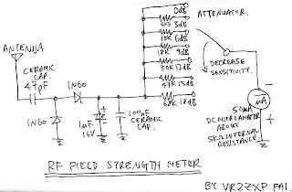
RF Field Strenght Meter with Attenuator up to 200 MHz

The RF field meter unit will be in great help to tune transmitters for best performances. You can measure the radiated energy field and can easy tune the system for max output field strength (maximum power).

RF Field Strength Schematic
This field strength meter with selectable attenuator. You can used it for measuring the antenna gain and pattern, compare different magnetic field strength. See the following RF field strength meter schematic.


RF Field Strength Features:
  • Input Terminal: SO-239 (M type) or BNC
  • Output Display: Analog power meter modify from a 50uA current meter and after calibrate with a RF generator.
  • Measuring Range: From +3dBm to -35dBm with attenuator. (0dBm = 1mW at 50ohms)
  • Operating Frequency: 100kHz to 200MHz
  • Power Source: No need.
  • Attenuator Range : With 6 ranges (0dB, 3dB, 6dB, 9db, 12dB, 15dB)
Source: Field strength meter with attenuator
read more "RF Field Strenght Meter with Attenuator up to 200 MHz"

100W RF Power Amplifier 50 MHz 2SC2782

This is a 6m band RF power amplifier (50 MHz) with 100W output. It used with my FT-736R and drive from 10W for the 6m SSB DX. The Building information comes from Japan CQ Magazine. The Toshiba RF bipolar power transistor will be used in it.

RF Power Amplifier Schematic and PCB


Grounding
If you want to construc this rf amplifier, it's the better way if the double side PCB use for increase the grounding and current transfer. The TX power can be tune to 120W.


RF Amplifier features:
  • Input Power: 10W
  • Output Power: 100W
  • Operating Frequency: 50-52MHz
  • Operating Mode: FM- SSB
  • Operating Voltage: 10-16V DC
  • Operating Current: 12A DC for 100W RF output
  • TX trigger:
  1. Trigger by internal RF power input detection circuit.
  2. Trigger by external equipment trigger output.
Download information (Japan CQ Magazine) page 1 page 2

Source: 6M 100W RF Power Amplifier
read more "100W RF Power Amplifier 50 MHz 2SC2782"

80W RF Amplifier 2SC2782 88-108 MHz

This is a RF power amplifier design using 2SC2782 bipolar transistors in a tuned class C circuit. The amplifier can be driven to full power with less than 1 watt driving power, so that a large gain margin results in this FM transmitter.

To obtain stability in this rf amplifier, I employed several techniques, such as placing the resonances of base and collector chokes far apart, damping the chokes with resistors, using RC combinations for absorption of unwanted frequencies, using feedtrough capacitors for bypassing on the board, etc. It took some tweaking, but the amplifier ended up unconditionally stable.


RF Amplifier Low-pass filter
This amplifier has a low-pass filter at the output, resulting in a signal clean enough to be directly connected to an antenna. The SWR meter was placed before the filter, in order to clean out the harmonics produced by its diodes. In any case, while the signal is clean enough to easily satisfy usual legal and technical requirements, this transmitter should not be used at a multi-transmitter site without further narrow band filtering!


This is so because any other strong signals on nearby frequencies would be picked up by the antenna and coupled to the power transistor, which would mix it up with the own signal, creating a wide array of intermodulation products, some of which would be re-radiated! This is a common and very big problem in many multi transmitter sites. In such places, not even one FM transmitter should be allowed on the air without narrow band filtering! Such filtering is easily accomplished by means of a single tuned cavity, which can be constructed from copper tubing or sheet.

RF Amplifier PCB


Here is the PCB layout, including the microstrips. The board is 20cm long and is double-sided, with the backside being a continuous groundplane except for two small pads at the driver transistor base and collector. I cut out these pads with a knife, rather than making a whole computer drawing for that!

Source: RF Power Amplifier 80W 2SC2782
read more "80W RF Amplifier 2SC2782 88-108 MHz"

RF Power Amplifier Module S-AV10H TOSHIBA

Here's an interesting S-AV10H TOSHIBA RF Power Amplifier Module circuit. It can deliver over 14W with as low as 100-200mW input power. The system is tuned for 50 ohm input and output. The frequency can be 150-175MHz. This is how the Module looks like.


To the left is the power input pin. Then comes power control, main power line and to the right is the output power. As you see there are quit many components inside and both input and output are matched to 50 ohm.


RF Power Amplifier Module S-AV10H TOSHIBA Schematic
The main part of this project is an oscillator which you will find on the left side. It is an oscillator based around Q1. L1 and C1 forms the tuned oscillating unit. The unit can easy be set from 100 to 200MHz by changing C1 and spacing/compressing the aircoil L1. You can see the air coil at the botoom left corner on the first photo at this page. Q2 works as a booster and amplify the power to 150mW.


The RF signal then enter the Module at pin 1. Pin 2 is a power control unit of the Module. The voltage at this pin will set the output power of the Module. A voltage stabiliser LM317 is added to generate a variable voltage from 1.25V to 12 V. You can see it in the middle of the PCB and in front if it is a 10 turn potentiometer (P1). An inductor blocks RF from the Module to pass out to the power line of the LM317. Pin 3 of the module is the main power input which also is RF blocked by an inductor. Theses inductors are not critical in any was, make sure they can handle high currents since the module will consume high current.
Pin 4 of the module is the power output matched to 50 ohm system.

You must use a dummy resistor of 50 ohm else you will destroy the module. Make sure you choose a good resistor which can handle 30-50W. Make sure you have placed the Module to a heat sink becasue it will be hot.

RF Power Amplifier Measurements
The output power from this module could be set from a few mW to about 18 W by the voltage at Control pin. The unit was stable down to 145MHz and current was about 2.2A at max output power.

Source: RF Power Amplifier Module
read more "RF Power Amplifier Module S-AV10H TOSHIBA"

Simple RF Field Meter

This circuit is a simple RF field meter. It will be in great help to tune transmitters for best performances. Not everyone has a power meter, and how can you know that the antenna you connect is purely 50 ohm. The next block diagram show you one easy way to measure the RF field strength. To the left you find a dipole antenna.


The antenna should be cut to match the receiving frequency. The length of antenna is not a critical at all.

Length = 0.95*300/(4*freq) <= (freq = MHz) 

The RF signal is then rectified in a diode and the DC voltage is then amplified in an OP-amplifier. To display the voltage I use a panel meter. The amplifier gain can be set with a potentiometer and I have also added a bias voltage to set the zero level of panel meter.

How To Use RF Field meter
  • Place the RF field meter 5 meter away from my transmitter.
  • Then put all variable capacitor to middle.
  • Switch on the transmitter and go to my RF filed meter.
  • Then set the gain (with potentiometer) so I get half of max reading on the panel meter.
  • Then switch off the transmitter and set the offset (with other potentiometer) so I get zero reading on the panel meter.
  • Repeat this tuning process unit it looks good.
Now I can start tuning the transmitter and watch the panel meter. All I need to do is to tune for max reading on the panel meter. Then I know the RF field is at max strength. I also advice you too receive the signal you are transmitting to check that it sound good. I also check the current to the transmitter so it don't get to high.

Usually the current go down when good tuning has been done and you got max power. Another good thing to monitor is the temperature of the transistors. Don't let them go to hot.

I find my RF field meter to be a very simple and powerful too. This RF filed meter works from 30mW to several watt.

RF Field Meter Schematic
At the bottom left corner you will see a voltage divider. This divider is to produce a virtual ground of 4.5VDC. Above you will find the dipole antenna. The dipole antenna will pick up some radiated energy and the diode will rectify the RF signal to a DC voltage at VRF. This voltage is still quit low and needs to be amplified before it can control the panel meter.


The signal then enter the OP which amplifies the voltage to suitable level set by the "Gain" potentiometers". The second OP acts as a voltage follower and set the offset (zero) for the panel meter. The panel meter is connected to the board via two wires (5meter long).

To prevent any RF signal to be induced in this long wire I have added 2 ferrite block which will act as high impedance units. You can use any ferrite block or large inductor (10uH).

Source: RF Field Meter
read more "Simple RF Field Meter"

1W VHF RF Amplifier 2SC1970 88-108 MHz

This RF power amplifier is based on the transistor 2SC1970 and 2N4427. The output power is about 1.3W and the input driving power is 30-50mW. It will still get your RF signal quit far and I advice you to use a good 50 ohm resistor as dummy load. To tune this amplifier you can either use a power meter/wattmeter, SWR unit or you can do using a RF field meter.


RF Amplifier Assembly
Good grounding is very important in a RF system. I use bottom layer as Ground and I connect it with the top with wires to get a good grounding. Make sure you have some cooling at the transistor. In my case I put the 2SC1970 close to the PCB to handle the heat. With good tuning the transistor shouldn't become hot.

RF Amplifier Printed Circuit Board
You can download a pdf file which is the black PCB. The PCB is mirrored because the printed side side should be faced down the board during UV exposure. To the right you will find a pic showing the assembly of all components on the same board.

This is how the real board should look when you are going to solder the components. It is a board made for surface mounted components, so the cuppar is on the top layer. I am sure you can still use hole mounted components as well.


Grey area is cuppar and each component is draw in different colours all to make it easy to identify for you. The scale of the pdf is 1:1 and the picture at right is magnified with 4 times. Click on the pic to enlarge it.

Low-Pass Filter
Some of you might want to add a low-pass filter at the output. I have not added any extra low pass filter in my construction because I don't think it is needed. You can easy find several homepages about low pass filter and how to build them.

Source: 1.3W Power Amplifier
read more "1W VHF RF Amplifier 2SC1970 88-108 MHz"

Thursday, November 22, 2012

28W RF Amplifier for FM Broadcast 88-108 MHz 2SC1946

This RF Amplifier designed for FM broadcast using a single 2SC1946 VHF Power Transistor. This 10-30W RF amplifier circuit provides an appropriate power boost with an input of 1-3 watt. Tower are 30 meters high will send signal surrounding air should be around 15 km.

RF Amplifier Artwork
The layout of the 2SC1946 28 Watts FM broadcast RF amplifier has been created with sPRINT Layout v3.0. You can get a Shareware copy at: http://www.abacom.de. The pcb outline is 100 x 50 mm (width x height), all bitmaps have a resolution of 600dpi.Use FR-4 single sided photoresist epoxy pcb material for best results.


RF Amplifier Parts List
All component values are drawn on the .comp and .silklayer bitmaps, with the following exception(s);
all four (4) coils (in the lowpass filter section) are: 3.5 turns, 8 mm DIA., 1.2 mm CuL closewound i.e. no wirespacing.


Note:
CuL = magnetwire, enameled copper wire, insulated (rigid) copper wire e.t.c..
2 mm equals approx. to #12 A.W.G
1 mm equals approx. to #18 A.W.G
1.2 mm equals approx. to #17 A.W.G
0.8 mm equals approx. to #20 A.W.G
0.3 mm equals approx. to #28 A.W.G.)
  • all diameters are measured from the inside of the coils, i.e. 'internal' diameter.
  • make sure to mount the rf-transistor on a appropriate heatsink and use some thermal heatsink compound between the flange of the transistor and heatsink! (Thermal resistance heatsink at least 6°C/W.)
Source: http://www.3-mtr.info/shareware/Amplifier%2028Watt%20MicroStripline%20(2SC1946A)/
read more "28W RF Amplifier for FM Broadcast 88-108 MHz 2SC1946"

20W VHF Linear Amplifier 2SC1946 50 MHz

This VHF linear amplifier works for 50 MHz frequency using 2SC1946A with power output about 20 Watt. It needs input 30mW and output 25W for 150 Mhz. It seems can be used for 144 Mhz without modification. There are Power IC and 2SC1946A with low-pass filter on the board.


Some Experiences
I have checked Mitsubishi Catalogue and found it is 175 Mhz(ft), 3W input - output 30W(at 13.5Vcc), Gp10dB. I reffered Linear Amplifier Hand Book for deciding capacitors and coils. I made PCB with cutting by cutter knife and removing by heat with solder tool.


After mounted all parts on the board, I tried to adjust SWR for input. Connect SWR meter between rig and linear amplifier and connect 50 ohm dummy load. Without power source for linear amplifier, I have to adjust SWR as it becomes lower (at least less than 1.5).

With adjusting TC, I could get about 20 Watt. And then I connected Omron Relay (G5V2) for input/output circuit and I adjusted again, after that I noticed power was less about 10W-12W.


I tried to adjust SWR to be 1.0 by changing coils. I have changed input/output coils from 2 turns to 3 turns and I could get SWR 1.0. After I got SWR 1.0, output power becomes about 25Watts but moduration was not good and seems self oscillation. I have changed input ATT with 6dB and after that moduration becomes good with 20W output.

Author: JO1ACW
Website: http://www.geocities.co.jp/Technopolis/7222
read more "20W VHF Linear Amplifier 2SC1946 50 MHz"