Sunday, February 26, 2012

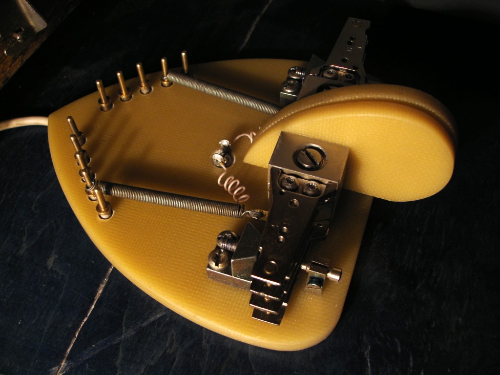
Junkyard Warz Novelty Transmitter by W9QZ


Several month ago I found a great, probably most artistic Glowbugs Radio homebrewer in the WEB - Rick Weber, W9QZ. I've been very impressed, downloaded some beautiful photos of those stylish Rick's HAM-Radio artefacts and, naturally, forget to check this page again - it was my mistake. Take this:


JunkYard D.I.Y. Transmitter


Rick:

"Junkyard Warz Novelty Project. This is a working Hartley transmitter I built with all non-radio components except for one 027 vacuum tube."

Visit W9QZ Vintage Gears and enjoy the fire of these FireBottles (not only fire - you can find some bottles turned  into HF insulators in the Lab of Great Steampunk Wizard, W9QZ)


Reblog this post [with Zemanta]
read more "Junkyard Warz Novelty Transmitter by W9QZ"

Saturday, February 25, 2012

ONER TCVR

Recent questions on this on GQRP list about the docs for the setup of a TCVR using a set of boards from Kanga a few years ago... basicalkly starts off with the ONER TX from George Burt GM3OXX

> SPRAT has them all...
>
> SPRAT 45 Pages 4 & 5 ONER TX
> SPRAT 53 Pages 4 & 5 ONER VFO
> SPRAT 54 Pages 16 & 17 ONER 'IMP' RX
> SPRAT 56 Pages 3 ONER changeover and wiring for the whole setup on page 4.
>
I only know as I put the components together to build, in an OXO tin and printed them off (GQRP CD has the SPRAT as PDF).

I had to sub in a few things though.
IRF510 for VN10KM (N channel mosfet)
2N3906 and 2N3904 were used where NPN and PNP appeared.
I used J310 instead of 2N3819 in the VFO and RL1 from the ONER changeover was DPDT relay PCB mount version from Jabdog.
read more "ONER TCVR"

Friday, February 24, 2012

Testing Audio Transformers


(Circuit for meter details at bottom)
As I am probably daft playing with valves I had to figure out some things for AF transformers and such like.

This was written by Brian Clarke VK2GCE and appears (to me anyway) to be the clearest description of how to do it with minimal kit. My notes in bold after each section.

Testing audio transformers

© Brian A Clarke VK2GCE

1 Test equipment required

Multimeter – analog or digital

Audio signal generator – fixed frequency or variable (I have a cheap Maplin kit that does sine, saw, ramp and square waves from about 10Hz to about 25KHz, I added a little speaker so I can monitor the tone and a little frequency counter as well but they are not nesessary). If don't have one then look for a circuit for an AF generator, it really doesn't have to be complex and could be build ugly style.

Variable resistors, 1off 25k to 50k and 1off 10 Ohm to 500 Ohm (Carbon, I found wirewound will add errors to measurements)

Connecting leads


Audio voltmeter- preferably calibrated in dBm, sensitive down to –60dBm
(I use an analogue meter, dad gave me a while back no markings or who made it. Audio philes may hate me saying this but I just want rough tests and not HiFi testing so this is also true, audio is AC, as long as your meter doesn't have any unusual restrictions about frequency response (most DVM don't work well at AF), you should be good to go. Set up a 1khz tone (just a bit higher than a normal 700-800Hz cw side tione) and plug it into the AC inputs of the voltmeter and see what you get, if you get almost no response you can't use it, that simple). You could attempt to build an Audio voltmeter too, at bottom of post I include one possible circuit, or use an oscilloscope like this one http://rf.circuitlab.org/2011/12/oscilloscope-kit.html but I was trying to limit the kit list!

2 Identify windings

Use the multimeter to identify continuity between the various connections.
For an output transformer, the high resistance winding, single ended or center-tapped is the primary
For a microphone, line or an inter-stage transformer, the higher resistance winding is usually the secondary
For
centre-tapped windings, the two halves may not be exactly the same resistance, especially on E+I cored transformers
There may also be a screen winding, which may or may not be connected to the frame.

3 Measure dc resistance

Use the multimeter to measure the dc resistance of each winding; write this down.

4 Measure impedance

4.1 Output transformers

  1. Connect the 100 Ohm variable resistor across the low resistance winding; initially, leave one wire open;

  2. Connect the 25k variable resistor in series with the high resistance winding and the output of the signal generator; set the resistance to 0 initially;

  3. Set the signal generator to 1kHz and near maximum output, which may be say, 20V rms

  4. Use the audio Voltmeter to measure the input and output Voltages; write these down

  5. Calculate the turns ratio = VIN/VOUT

  6. Connect the 100 Ohm resistor in circuit

  7. Reduce this resistor till the output Voltage falls 3dB (i.e. halves!)

  8. Increase the 25k resistor till the output Voltage falls another 3dB (i.e. halves!)

  9. Without disturbing the settings of the variable resistors, disconnect one lead from each

  10. Use the multimeter to measure the settings of these two resistors – these are the impedances of the primary and secondary – you may need to replace the 100 Ohm

    variable resistor with a lower value to get an accurate measure (I replaced with a sliding pot and fixed value resistors getting a rough value)

  11. Compare the turns ratio with the impedance ratio – do they agree? Allow for the dc resistance of the windings

4.2 Microphone, line and inter-stage transformers

Follow the procedure for output transformers, except:

  1. Connect the 25k Ohm variable resistor across the high resistance winding; initially, leave one wire open;

  2. Connect the 100 Ohm variable resistor in series with the low resistance winding and the output of the signal generator; set the resistance to 0 initially;

  3. Set the signal generator to 1kHz and low output, which may be say, 20mV rms (I used a Maplin AF sig gen)

Warning: do not exceed 20mV rms for microphone transformers

  1. As above

  2. As above

  3. Connect the 25k Ohm resistor in circuit – it may have to be a higher resistance;

  4. As above

  5. Increase the 100 Ohm resistor till the output Voltage falls another 3dB (i.e Halves)

  6. As above

  7. As above

  8. As above

5 Measure frequency response

Note: this section can only be done with a variable frequency signal generator.

  1. Reconnect the variable resistors without changing their settings

  2. Connect the audio Voltmeter across the secondary (I used the meter I mentioned, some DVM will not work!)

  3. Reduce the frequency till the output falls another 3db compared with steps 8 above; this is the lower 3dB point (My audio sig gen is brilliant for this you just press a button and the signal drops and you watch the meter)

  4. Increase the frequency till the output falls another 3db compared with steps 8 above; this is the upper 3dB point (My audio sig gen is brilliant for this you just press a button and the signal rises and you watch the meter)

  5. Write this information down – perhaps attach it to the transformer. (Wrote on mine with CD pen)

6 Measure power response (I never did this bit)

If you want to measure power response of output and inter-stag

e transformers, you will need a very good quality power amplifier, high power non-inductive load resistors and a CRO.

  1. In place of step 1in section 4.1 above, use a variable high power load resistor to achieve the value found in step 10

  2. In place of step 2 in section 4.1 above, use a high power variable resistor to achieve the value found in step 10

  3. Connect the audio Voltmeter across the primary;

  4. Set the input power to about 1W

  5. Connect the CRO across the secondary. Set the signal generator to 1kHz

  6. Increase the power input until the image on the CRT just starts to flatten – this is probably 3dB over the rated power of the transformer

  7. Reduce the power input

  8. Change the input frequency to the lower 3dB point identified in step 3 of section 5 above

  9. repeat step 6 at this lower frequency – the low frequency 3dB point may be at a much higher frequency than the lower 3dB point at low power [section 5] – it depends on how powerful the accountant was with respect to the design engineer in choosing how much core of what quality to use.

Precision Audio Millivoltmeter
Measures 10mV to 50Volt RMS in eight ranges

Parts:

R1_____909K    1/2Watt 1% Metal Oxide Resistor
R2______90K9 1/2Watt 1% Metal Oxide Resistor
R3_______9K09 1/2Watt 1% Metal Oxide Resistor
R4_______1K01 1/2Watt 1% Metal Oxide Resistor
R5_____100K 1/4W Resistor
R6_______2M2 1/4W Resistor
R7______82K 1/4W Resistor
R8______12K 1/4W Resistor
R9_______1K2 1/4W Resistor
R10______3K3 1/4W Resistor
R11____200R 1/2W Trimmer Cermet

C1_____330nF 63V Polyester Capacitor
C2,C3__100΅F 25V Electrolytic Capacitor
C4_____220΅F 25V Electrolytic Capacitor
C5______33pF 63V Polystyrene Capacitor
C6_______2΅2 63V Electrolytic Capacitor

D1-D4___1N4148 75V 150mA Diodes

IC1_____CA3140 Op-amp
IC2_____CA3130 Op-amp

SW1_____2 poles 5 ways rotary switch
SW2_____SPDT switch

J1______RCA audio input socket
J2,J3___4mm. output sockets

B1______9V PP3 Battery

Clip for PP3 Battery

Notes:

Connect J2 and J3 to an DVM-meter set to maximum amp range

Switching SW2 the four input ranges can be multiplied by 5

Total fsd ranges are: 10mV, 50mV, 100mV, 500mV, 1V, 5V, 10V, 50V

Set R11 to read 1V in the 1V range, with a sinewave input of 1V @ 1KHz

Compare the reading with that of another known precision Millivoltmeter or with an oscilloscope

The oscilloscope reading must be a sinewave of 2.828V peak to peak amplitude

Frequency response is flat in the 20Hz-20KHz range

If you have difficulties in finding resistor values for R1, R2, R3 & R4, you can use the following trick:
R1 = 10M + 1M in parallel
R2 = 1M + 100K in parallel
R3 = 100K + 10K in parallel
R4 = 1K2 + 6K8 in parallel
All resistors 1% tolerance

Another option is here http://sound.westhost.com/project16.htm

This is all for AF.

For RF you might want to look at N5ESE RF inductance meter

http://www.io.com/~n5fc/l-meter.htm

read more "Testing Audio Transformers"

Tuesday, February 21, 2012

RF Amp


Most of my 30s vintage transmitters are in the 10-20 watt range. It would be fun to have a little more power, especially with my 10 watt Meissner Signal Shifter / VFO. According to the specs two Taylor TZ20s in push-pull can be driven with 5 watts to about 110 watts input or 85 watt output. This sounds like what I'm looking for.

As usual any project starts with sorting through parts and then doing a preliminary layout before taking a drill to the metal.
read more "RF Amp"

Second Life of Dead MFM Hard Drives - Iambic Paddle


Homebrew Iambic Paddle Just finished my first in life "Instructable" at the D.I.Y. host site instructables. It is short sketch about Iambic Paddle which has been made using a spare parts from the dead MFM HDD drive. I got a lot of fun posting to that site, and I think that it should be good idea to post more detailed article here. Frankly, this homebrew project is not a Pure Glowing Bug, but I'm not so puristic today.
Well, let me explain - why I decided to use HDD heads as a levers in this Iambic Paddle Project. For many years I've collected computer spare parts for no reason, just because I have a big, nearly endless Junk Box and it was impossible to me to throw such high-tech toys in the trash. But one morning I found that my Junk Box is full and The Time of Trash Bags has come. It was a hard work, but under the tons of debris I found the treasure - my first homemade Z80 Sinclair Spectrum and five old 5 inch MFM hard drives from my second computer.
As you remember, these drives was a big rounded shaped boxes, ideal as a chassis for any homemade electronic projects, tube glowbugs as well as solid state stuff. Another interesting things - powerful electromotor and magnetic cylinders itself, thick shiny discs which are so usable as a dial or scale part, looked much better than a CD in this role. And last but not least - yes, precision bearings on the easy to mount axis in magnetic head's block. What a beautiful hardware! When I opened and totally disassembled these hard drives, I realized that I literally had a very new telegraph key, usual one lever, dual lever iambic paddle or even straight key - not so important, it is easy to make any kind of telegraph manipulator using these nice spare parts. Watch this video demonstrating a working Iambic Paddle and take a look at step by step constructing process here:
READ MORE >>
read more "Second Life of Dead MFM Hard Drives - Iambic Paddle"

Monday, February 20, 2012

M1KTA shack almost finished reorganisation

No new builds for a bit as minor problem with shack roof and had to replace some of the felt. Only found problem when started to reorganise. I must have missed the problem when tree came down last year and side swiped the back of the shack. Anyway the roof is done and the internal reorganise is 50% done now so should be back melting solder shortly.

The Yaesu FT897D will be retired (not going to sell as useful rig for IOTA trips) and use one of the two QRP2004 rigs I built as the main station set. FT817ND will remain as /P bicycle rig.

Going to finish the M1KTA version of a phasing rig I had started to blog as well as a HB1A/KX1/Drew Diamond clone , I had the boards with me at GQRP Rishworth. Adding RIT to the SW20+ and building a kit and manhattan FtTuthill80 TCVR.

As I have a 500KHz NoV will be finishing off building a station too. 500KHz RX will be SDR with HB9DRV new SDR-Radio and I'll run a remote server so you can hear/see activity on 500KHz from JO02bd, TX will be DDS based driving a MOSFET. The shack line up of DDS is pretty excessive so going to prune a few but before do that going to do a side -by-side comparison. I recently added a K5BCQ DDS to the line up and going to see which is best for the 500KHz TX (with a 4020 or 4060 divide by 8).

The shack clear out I seem to have managed to sell most of it except the Norcal2030 partial kit (just the things you cannot buy from Digikey et al), PFR-3 and ATS-3 rigs. Will take a lot of the rest not on the blog to CDARC March 7th Rally as will run a GQRP stall with M5CHH this year. Need an ATX based PSU got plenty of units to convert and will have a completed example with me.

Scheduled to build a K1 for someone else as I am a UK Elecraft builder now.
read more "M1KTA shack almost finished reorganisation"

Friday, February 17, 2012

Big Nick and the Cydecos - Glowbugs Radio Hide-And-Seek


KC9KEP's ARRL 1941 7-Tube Superheterodyne Homebrew Radio
Today I decided to become (at very last) a real blogger and to invite some celebrities as a trendy stuff. But as it turned out, neither Madonna nor Britney Spears did not make the tube radios, Arnold Schwarzenegger is possible and would do, but too busy at work, and Michael Jackson .. Okay, let's not about sad - the result of my quest was a brilliant success:
READ MORE >>
read more "Big Nick and the Cydecos - Glowbugs Radio Hide-And-Seek"

Wednesday, February 15, 2012

Clearing M1KTA shack of some items

Clearing the M1KTA shack of built kits I am not using to make way for and raising a bit of cash for newer projects so have decided sell a few things, I will sell these at what they cost me, check the respective websites in the list for original details, or do a google search or look on eham.net or QRP-L.

Please contact me directly via email if interested. My email address in QRZ.com is valid.

I'll update this specific blog post with details and images and add to the list but possible items include:

1. Completed Norcal power meter. I purchased and assembled the kit in 2008, it even appears on the blog. The unit is in pristine condition and works perfectly. Never taken out of the shack. I am selling it because I'm not using it and have other power/SWR measurement options in the shack.

Here are some basic specs. See the Norcal website for more details.
Frequency range: 160 thru 10 meters
Power level: 0.1 to 9.9 Watts
Accuracy: +/- 10%
Insertion loss: 0.1 dB
Power: Internal 9V battery
Connectors: BNC

Both digital and analog power displays. PEP for sideband. Audio Morse
output also.

I checked the completed unit against a calibrated power meter (I had used a Bird Meter as the callibration standard) and there was no marked error across the frequency range.

I include an assembly and operating manual.

Promised elsewhere now.

2. KD1JV, Steve Weber, QBSA
This is the shack base accessory to the ATS-3 rig.
Description: Actual size, 3" long, 2.55" wide, 1.45" high.
• Digital Dial
• 0- 9.99 Watt power meter, Forward or Reverse power
• 2 Watt audio amp
• 6 to 11 volt variable voltage regulator
Designed primarily for use with the kd1jv ATS series rigs to enhance base station use of the rig, the QBSA can also be used with other QRP rigs. IF offset for producing direct reading digital dial is programmable and IF offset arithmetic operations are pin selectable.
The QBSA may also be useful on your work bench. The frequency counter is usable up to 45 MHz (100 Hz resolution), and the variable voltage regulator can deliver up to 1 amp of current if heat sinked.

This cost me $45 but never used, AVR not even mounted and still in the foam.

Check http://groups.yahoo.com/group/AT_Sprint/

3. KD1JV, Steve Weber, ATS-3B
This is a set of built boards and the LPF filters. The variable capacitors need to be added to the LPF and finally aligned but complete otherwise.

The notes on it say:
  • 3.1" x 2.2" board fits into standard Altoids tin.

  • Main board + one filter board weighs 1 ounce

  • 80/40/30/20/17/20 meter operation using plug in filter modules (supplied)

  • AD9834 DDS VFO for rock solid frequency stability

  • Sensitive 0.2 uV superheterodyne receiver

  • Double tuned receiver input filter for excellent image and out of band signal rejection

  • Four crystal IF filter and 600 Hz audio filter provide excellent CW selectivity and opposite sideband rejection

  • Audio AGC and limiting eliminates need for volume control.

  • Simple four push button, multi-function switches operate the rig.

  • RIT/XIT split modes

  • Unique "Direct Frequency Entry" using the paddle allows moving directly to any frequency in the band.

  • Single digit seven segment LED display for frequency readout and visual feedback, in addition to Morse annunciations.

  • Built in 5 to 35 wpm Iambic keyer, selectable A or B mode operation

  • Three keyer memories, up to 124 character total.

  • Reverse paddle sense option

  • Alternative "Stealth" paddle option allow use of tuning switches as paddles - saves additional weight by not needing an external paddle or use in emergency when external paddle or cable breaks!

  • 2.5 watt power output with 9 volt supply, over 4 watts with 12 volt supply - on all bands. Typical PA efficiency is over 70%

  • Modest 35 ma receive current for long battery life.

  • Operates down to 5.5 volts and transmitter still puts out usable power - 800 mw!

Cost me $200
Steve has retired this now.

Check http://groups.yahoo.com/group/AT_Sprint/

4.KD1JV, Steve Weber, ATS-3A kit unmade
Original cost $180
http://web.archive.org/web/20070103081702/kd1jv.qrpradio.com/ats3a/ATS3A.HTM

Check http://groups.yahoo.com/group/AT_Sprint/ too

5. KD1JV, Steve Weber, PFR-3
I built this whilst attending FDIM 2008. Ken Evans reviewed it in the QQ shortly afterwards.
qrpkits.com sells an updated version right now. I paid $200 for mine.
http://qrpkits.com/pfr3.html

6. MKARS80 SSB Rig and CW interface
G6ALU, bought mine at the Leicester rally and the CW interface later.
http://www.radio-kits.co.uk/mkars80page.html
I have a spare set of enclosures so you could improve on mine.

Promised elsewhere now.

7. BITX20A
Built qrpkits.com kit.

8. Tayloe SWR Indicator/Bridge built Kit
http://qrpkits.com/swrindicator.html

Promised elsewhere now.

9. Through hole Firefly 20m
http://qrpkits.com/firefly.html
Part built kit

10. SMT Firefly 20m
http://qrpkits.com/firefly.html
Unbuilt kit

11. Rockmites

12. Rockmite AF filter kits
http://www.qsl.net/n0rc/rm/builder_notes/rmaf/rmaf.html
http://web.archive.org/web/20070206191438/kd1jv.qrpradio.com/rmaf/RMAFB.HTM

13. Softrock V6.2 RX lite kits
Several bands

14. Norcal 2030 partial kit
http://www.norcalqrp.org/nc2030.htm
http://www.norcalqrp.org/nc2030partial.htm

15. KD1JV Switched Longwire Tuner from qrpkits.com
http://www.qrpkits.com/slt.html was $40

Promised elsewhere now.

16. Tenna Dipper
Two of these one is complete other still a kit of parts.

http://web.archive.org/web/20060205215329/www.4sqrp.com/kits/td/td.htm
Cost me $29 each

17. QRP2004 complete set of components for a build.
http://myweb.tiscali.co.uk/qrp2004/
£187 (cost price)

18. Norcal VE3DNL Marker Generator
http://www.norcalqrp.org/VE3DNLmarkergenerator.htm
Cost $10
read more "Clearing M1KTA shack of some items"

Monday, February 13, 2012

6P3 (6П3) Beam Power Tetrode

6P3, 6P3S, 6P3S-E vacuum tubes

6L6 vacuum tube has been introduced by Radio Corporation of America in July 1936 and since 1937 it began to be produced in the USSR on equipment provided by RCA. For the first time it was usual metal 6L6 , but later was chosen glass bulb design in order to avoid overheating, so just before the WWII tube factories started to produce 6P3 (6П3) valves (left on photo), which was actually Soviet version of 6L6-GB tube.


After the forties, design has been changed (center tube on the photo) and the new one got additional "S" mark, which meant "Oktal" according to the post-war standard specification. There was some modifications such as 6P3S-E (6П3С-Е) (at the right on the photo) and 6P3S-EV (6П3С-ЕВ). I heard a lot of controversial stories about these extra letters, but according to the GOST it is Durability (E) and Reliability (V), so 6P3S-EV is just a high mechanical quality version of general 6P3S (6П3С) with warranted lifetime, probably military or industrial purpose. As for claimed electrical parameters, these 6P3S-E (6П3С-Е) and 6P3S-EV (6П3С-ЕВ) tubes has less current and voltage deviations than common 6P3S but according to my subjective opinion WWII 6P3 tube was a best performer in this family.


Naturally, 6P3 tube has always been one of the most popular in a variety of radio enthusiasts, it can be found in a Hi-End audio amplifier as well as in a HAM-Radio transmitter. BTW, not only HAM-Radio - it was and it is The Legendary Tube of the xUSSR Radio Pirates. Every Pirate Newbie starts with "The Whistle" - classical simple one 6P3S tube AM transmitter and so remarkable that a main web site of these guys is http://6P3S.ru


READ MORE >>
read more "6P3 (6П3) Beam Power Tetrode"

Saturday, February 11, 2012

500kHZ NoV Application Success!

As they say if at first you don't succeed try again.... OfCom have just granted an SRP to M1KTA for 501-504kHz and will be active on the band asap.

For those interested my application supporting docs.

http://m1kta.ham-radio-op.net/m1kta/hidden/500khz/500khz_nov.doc
read more "500kHZ NoV Application Success!"

Friday, February 10, 2012

5MHz NoV

My new 5MHz NoV arrived today, I let the old one lapse.

So should be QRV on 5MHz again soon.
read more "5MHz NoV"

/P from Snettisham

For those that might have worked me and wondered about the location as different to the one in qrz yes it was me /P from Snettisham yesterday (9th Feb).

Testing another antenna on the beach as well as using the trusty W3EDP on 80m.

Am building a /P DX trip rotatable wire 2 el vertical beam for 15/17/20m using 12m fishing pole using an IP56 ABS box to hold the balun, feeder etc and a cross member made from a couple sections of 5m fishing poles. It was a bit windy yesterday and I lost my reference buddipole as it blew over and managed to snap the whips off (again!)

Managed a nice chat with EI4IT, who was /P also in Donegal about the Lough Erne Rally 11 April. As MI5MTC said:

News item for RSGB news on Sunday 14 February 2010

Rev. George Dobbs, G3RJV is the world’s best known QRP enthusiast. He will attend a major QRP display at the Lough Erne Amateur Radio Club Rally on Sunday 11 April. The Rally is again in SHARE on the shores of Lough Erne, where islands abound with remains of ancient Celtic Christianity, George’s other keen interest.

Graham Firth, G3MFI, who is another listed in the International QRP Hall of Fame, is bringing the entire G-QRP Club stall, with lots of interest for low-power radio amateurs, and those intrigued by building their own rigs. Graham will also tour the Erne’s historic Second World War flying boat sites in the Battle of the Atlantic . On a second QRP table, Dom Baines M1KTA will display home-built kits, receivers, transmitters and accessories, similar to his very popular exhibition at the recent GQRP Convention. This will be another excellent opportunity to examine, ask questions and get expert advice from a master kit-builder.

A third display will be set up by Brendan Minish EI6IZ, from the Mayo Radio Experimenters Network. His will feature top quality Elecraft QRP kits from the USA , with much good advice from Brendan for novice and experienced kit builders alike. Along side he will have Elecraft’s latest high power K3 kit to build your own rig to standards of quality that match the best on the amateur radio market.

So, for all radio amateurs and experimenters interested in today’s thriving and traditional heart of amateur radio, home construction and low power operation, the place to be on Sunday 11 April has to be the Lough Erne Rally in Fermanagh , Northern Ireland . Details are on the usual rally lists.

Enquiries to Michael Clarke, Mi5MTC, Chairman Lough Erne ARC

read more "/P from Snettisham"

Sunday, February 5, 2012

1929 and 1930 Stations

Lots of times questions get asked about what sort of rig to put on the air as a 1929 station. What were hams really using? Do the back page ads in QST really reflect what was on the air?

As I went through my old issues of the AWA OTB/Journal I found Bruce Kelley's comments on 1929 equipment in the May 1994 issue. He summarized 1929 and 1930 QSL card information from W1NE. He saw that Hartley oscillators and the 210 dominated the transmitter scene and almost 90% of the receivers had no RF stage. I found two 1930 QSL cards in my collection and added those to Bruce's tabulation. I've posted this data at http://www.prismnet.com/~nielw/OldQSLCardInfo2.pdf .

If you have similar 1929 or 1930 QSL data email it to me and I'll add it to the summary.
read more "1929 and 1930 Stations"

Friday, February 3, 2012

WHITE PENTAX K-x 12MP DSLR CAMERA w/18-55 LENS KIT

The K-x combines solid photographic performance with a wide array of advanced features at an affordable price. It features PENTAX's innovative in-body Shake Reduction mechanism for sharper blur-free images, 12.4 megapixel CMOS sensor, comprehensive Dust Removal system, HD movie capture and high-speed continuous shooting of approximately 4.7 frames per second in its ultra-compact body. These features, along with the user-friendly PENTAX-original Auto Picture mode and Live View with a choice of three different focusing modes assure great results every time.


This K-x one-lens kit includes the smc PENTAX-DA L 18-55mm F3.5-5.6 AL lens which covers the wide-angle to medium-telephoto ranges.

High-quality image reproduction
The 12.4 MP CMOS image sensor assures high-speed image data readout and more flexible response to varying ISO sensitivity levels and can faithfully and accurately reproduce true-to-life images with fine detail and rich colour depth. It not only offers a wide sensitivity range between ISO 200 and ISO 6400, but also allows you to expand the sensitivity range between ISO 100 and ISO 12800 via a custom function, giving greater creative freedom to the more adventurous photographer. The PRIME (PENTAX Real Image Engine) II imagine engine, offers greater data processing speed and enhanced capability to produce higher-quality images with richer, more accurate colour rendition, as well as faster transmission speed of movie data.


High-precision 11-point AF sensor
The wide-frame SAFOX VIII autofocus system features 11 sensor points (with nine cross-type sensors positioned in the middle) to automatically capture even off-centered subjects in sharp, crisp focus. Select from 11 or 5 points or manually select any one of the sensors as the focusing point to accommodate specialized applications.

Compact, lightweight body
Despite the incorporation of the large 23.6mm x 15.8mm image sensor, the K-x is one of the most compact, lightweight digital SLR cameras available. It offers easy one-handed operation.


Live View function with choice of three focusing modes
The Live View function allows you to view the image on the LCD monitor during shooting. Select from a choice of three different focusing modes during Live View shooting: Contrast AF, which optimizes the focus based on the subject's contrast; Face Detection AF, which automatically detects up to 16 faces, selects the main subject's face from multiple faces, then captures it in sharp focus; and Phase Difference AF, which uses the AF sensor positioned in the camera body to optimize focus on the subject. Coupled with the half press focus activation, this gives unprecedented ease of use in Live View.

HD Movie Capture
The movie recording function extends the benefits of high-quality SLR photography to the world of movie shooting. It captures beautiful, true-to-life movie clips in 16:9 high-definition TV proportions (1280 x 720 pixels) at a frame rate of 24 frames per second.

PENTAX-original SR (Shake Reduction) mechanism
The PENTAX-developed SR (Shake Reduction) mechanism effectively compensates the adverse effect of camera shake by as much as four shutter steps, assuring sharp, blur-free images even under demanding shooting conditions. This innovative mechanism is compatible with almost all existing PENTAX interchangeable SLR lenses – both old and new.* * Lenses compatible with this mechanism are the PENTAX K-, KA-, KAF-, KAF2- and KAF3-mount lenses; screw-mounted lenses (with an adapter); and 645- and 67-system lenses (with an adapter). Some functions may not be available with certain lenses.

High-speed continuous shooting
The K-x's high-speed continuous shooting mode records as many as 17 images (in JPEG recording format) at a maximum speed of approximately 4.7 images per second at 1/125 second shutter speed – the fastest of all entry-class models. Its top shutter speed of 1/6000 second allows you to preserve sharp, crisp images of fast-moving subjects.

Innovative image processing functions to produce distinctive photographic effects
(i) Digital filter function
This function allows you to process recorded images in a variety of creative ways within the camera and produce highly creative visual expressions. With a choice of 16 different filters, you can even apply different filters, one after another, to a single image to create more personalized visual effects.
(ii) Cross process mode
The K-x features the new cross process mode, in which the camera automatically and randomly shifts photographic parameters for each exposure to create eye-catching images with unique colours – just like pictures treated with the cross process*** in film photography. This playful mode adds the elements of surprise and unpredictability to digital photography as you cannot expect the outcome until the captured image is actually displayed on the camera's LCD monitor. *** A film development technique that takes advantage of unconventional film developers to create a distinctive finishing touch with intriguing colours.

Other features
  • Energy efficient circuit design for longer battery life, capable of capturing approximately 1,900 images with four AA-size lithium batteries
  • Custom Image function to create unique finishing touches including the exclusive PENTAX B&W Infrared Mode DR (Dust Removal) mechanism to eliminate dust spots on recorded images and DUST ALERT to visually check for the adhesion of dust to the image sensor.
  • 2.7-inch, high-resolution wide viewing angle colour LCD monitor with approximately 230,000 dots Auto Picture mode for effortless, automatic selection of the most appropriate shooting mode, even during Live View shooting
  • HDR (high dynamic range) function to create one composite image with an extra-wide dynamic range from three different exposures
  • White balance control, featuring a new CTE mode to emphasize the colour components of sunset scenes features preview of the white balance while adjusting settings. The white balance can be saved from an existing image
  • Status screen for easy, at-a-glance confirmation and adjusting of various settings on the LCD monitor
  • Ten scene modes, with selection via simple icons
  • Automatic compensation for lens distortion and lateral chromatic aberration (available only with DA and D FA series lenses)
  • In camera RAW processing of single or multiple images is possible with adjustment of the image parameters.
  • Includes the PENTAX Digital Camera Utility 4 software package, with RAW-data processing and browser applications


  • read more "WHITE PENTAX K-x 12MP DSLR CAMERA w/18-55 LENS KIT"

    Thursday, February 2, 2012

    Tokyo Hy-Power HL-1.2Kfx High Frequency Linear Amplifier.

    The HF Linear Amplifier of choice and operation currently with my Yaesu FT-2K is the Tokyo Hy-Power HL-1.2Kfx which is entirely solid state, has a small foot print, require no-tune, just plug and play.

    This world-class compact amplifier is the easiest to handle and operate. Main PA section includes 4 high power MOS FET SD2933's.The amplifier's broadband characteristics require no further tuning once the operating band is selected.


    Frequency Range 1.8 - 28MHz all amateur bands including WARC bands
    Mode SSB / CW / RTTY
    AC Power AC 100/110/115/120V, AC 200/220/230/240V
    RF Drive Power 85W typ. ( 75 - 95W max.)
    Output Power SSB 750W PEP max., CW 630W, RTTY 400W
    Final Transistor SD2933 x 4 ( MOS FET by ST micro )
    Circuit Class AB parallel push-pull
    Cooling Method Forced Air Cooling
    Multi - Meter Output Power Pf 1kW, Reflected Power Pr 100W,
    Drain Voltage Vd 60V, Drain Current Id 50A
    In/Out Connectors SO - 239 ( Type M-J )
    Dimensions
    (W) x (H) x (D)
    Approx. 232 x 142 x 350 mm
    Approx. 9.1 x 5.6 x 14.3 inches
    Weight Approx.15 kgs./ 33 lbs.
    Optional Accessories AC Power Cord x 1, RCA Plug x 2, Spare Fuse 8A
    ( for AC230V line ) x 2, Spare Fuse 15A ( for AC115V line ) x 2, Spare Fuse 1A x 2, Spare Fuse 2A x 1, User Manual x 1
    read more "Tokyo Hy-Power HL-1.2Kfx High Frequency Linear Amplifier."