The RF Oscillator is based on a Hartley oscillator. The frequency is determined by L1 and capacitor C1. The Vtuning voltage will change the capacitance in the varactor BB132 wich will change the oscillation-frequency. The value of capacitor C2 will determine how much the frequency can be changed by the tuning voltage. The larger value the more the frequency will change.
This Oscillator Circuit is based on two dual-gate FET. First FET is a Hartley oscillator where the frequency is determined by the value of L1, C1, C2 and the varicap diod. C2 set the span of the VCO. The second FET is just an amplifier. The gain is less than 1, but the current will be higher and the oscillator will not be loaded. The output amplitud changes depending on the frequency and how many turns there is on L1. By changing the voltage on g2 at FET1 you can set the amplitud. By adding a resistor to ground you will lower the amplitudo.
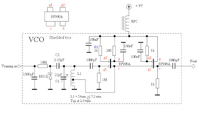
In this schematic I have conected g2 to Vcc (through R1) wich will give the highest gain.
VCO have made some test with different coils. The diameter of L1 is the same 7.2mm
but I have changed the turns to 3, 4 and 5. The diagram at the right shows the Amplitudo and the frequency. You can also se the range of this VCO. During the test the varicap was removed so the tuning range is set by C1. The best way to get the oscillator work is to attach a oscilloscope to the output. If the amplitud of the oscillator is low, you must move the tap-point a bit. The best way is to make 3-4 coils with the tap-point at different places and test each coil before you decide wich one you will use. The amplitud from my VCO is about 200mVRMS at 100MHz.

Remember: When you are building oscillator you must keep the wires short and shiled the oscillator! then it will work nice.


No comments:
Post a Comment