Sunday, April 24, 2011

Miniature Transmitter For Small Bird

Introduction
The goal of this project was to build a small, cheap, light-weight telemetry transmitter to attach to a small bird.
Specifically:
* Telemetry Tranmission should be tuned to the 2-meter band.
* Battery life in the field should exceed 3 months without replacement.
* Range should be 500 meters.
* Weight less than 10 grams.

The Circuit
This wireless telemetry transmitter circuit shown was originally designed by William Cochran (1), with modifications by Charles Walcott.


Reference
1. William W. Cochran; Rexford D. Lord, Jr., A Radio-Tracking System for Wild Animals,
The Journal of Wildlife Management, Vol. 27, No. 1. (Jan., 1963), pp. 9-24.
read more "Miniature Transmitter For Small Bird"

Tuesday, April 19, 2011

Miniature Telemetry Transmitter

Telemetry or "remote measurement" is a highly automated communications process by which measurements are made and other data collected at remote, inaccessible or dangerous places, and then relayed by a telemetry transmitter to receiving stations for display, monitoring, and recording. The original telemetry systems were termed "supervisory" because they were used to monitor electric power distribution. Communication channels form a major part of any telemetry system, as it involves measurement of the transmission of data over various mediums.

Telemetry transmitter is the instrument used for recording the readings of an instrument and transmitting them by radio or wireless frequencies. Technically, when relaying data, it is necessary for the transmitter to identify the data item corresponding to each segment of the bit stream. This is done by inserting a synchronization bit string into the telemetry stream on a regular basis, usually at the beginning or end of each repeating cycle. This generally corresponds to the beginning or end of a minor or major frame of telemetry data.

Aerospace telemetry initiated in the 1930s with the radiosonde, a instrument that automatically measured atmospheric temperature, pressure and humidity by means of a small, expendable telemetry transmitter from a balloon high in space, and relayed the data back to Earth using radio signals. These days, telemetry is used in testing of moving vehicles such as cars, aircrafts, missiles and satellites. National Aeronautics and Space Administration (NASA), European Space Agency (ESA) and other international space agencies use telemetry transmitters for data collection and transmission from orbiting spacecrafts and satellites.

Wireless networking without the encumbrance and restriction of wires connecting the transmitter and receiver has catapulted the potential applications of telemetry. Major applications of telemetry includes automatic monitoring of large, complex systems such as satellites, chemical plants, oilrigs, electric power plants, gathering meteorological data, remote meter reading, logistics management, tracking endangered land and marine species, real time physiological monitoring of patients, and monitoring manned and unmanned space flights.

Winston Churchill once said, "The price of greatness is responsibility." In the same manner, this great technology should be used responsibly. For instance, for many environmental monitoring duties, such as stream gauging or automatic weather stations, the measurement values are unlikely to change significantly for many hours at a time. In such cases, it would be grossly uneconomical in terms of both electrical power and use of spectrum space to run the telemetry transmitter continuously.
read more "Miniature Telemetry Transmitter"

RF Filter Types

An RF filter is an electrical circuit configuration (network) designed to have specific characteristics with respect to the transmission or attenuation of various frequencies that may be applied to it. There are three general types of RF filters:

A high pass filter similarly has a cut-off frequency, above which there is little or no loss in transmission, but below which there is considerable attenuation. Its behavior is the opposite of that of the low-pass filter.


A low pass filter is one that will permit all frequencies below a specified one called the cut-off frequency to be transmitted with little or no loss, but that will attenuate all frequencies above the cut-off frequency. High-pass and low-pass filters can be difficult to construct properly. Whenever possible, many amateurs simply buy them.


A band pass filter is one that will transmit a selected band of frequencies with substantially no loss, but that will attenuate all frequencies either higher or lower than the desired band.

read more "RF Filter Types"

RF Power Amplifier Design Formula

An RF power amplifier is a type of electronic amplifier used to convert a low-power radio-frequency signal into a larger signal of significant power, typically for driving the antenna of a transmitter. It is usually optimized to have high efficiency, high P1dB compression, good return loss on the input and output, good gain, and good heat dissipation.

Wideband Amplifier Design

transformations over large bandwidth are difficult to realize, thus most wideband amplifiers use 50 Ω output loading. Transistor output power is then limited to


Vbr
is defined as the breakdown voltage
Vk is defined as the knee voltage and
read more "RF Power Amplifier Design Formula"

Saturday, April 16, 2011

Audio Video Wireless Transmitter

In this fast-paced world, there is little time for inconveniences and a greater need for portability and adaptability. The idea for an Audio/Video transmitter stems from this need. There may have been times when you've wanted to hook up your VCR from one room to another television set in another room.

But that would have entailed that you first unhook all kinds of wires and plugs from the primary TV set; carry the VCR to the next TV set; and then finally re-wire everything together. An Audio/Video transmitter will let you do just about the same thing. But it would offer other conveniences as well. For example, it would allow you to set up security cameras around your home which would send video signals directly to a TV or VCR. And, there are no cumbersome wires and cables to line throughout the intended area.The most difficult part of this project was coming up with a design that would work. Because both of us had very little experience with RF signal systems we had to learn, basically, from scratch. The approach we took, was to first create a video transmitter, then add the audio portion later. This way we could test each component individually and then integrate them later when we knew both parts were working correctly.

We first went to the Grainger Library to research various transmitters designs and how they were built. Although all the books were very old, we were able to gather some useful information from various sources. Most of the books had only information about sending audio transmission and had very little on video signal transmissions. Also, some books that had some kind of designs and data for video tranmission were very outdated.

But we found some interesting standards that help explained what television stations used. This was not too far from what our original intentions were on building two different types of transmitters. Let us first look at the basic block diagram of what and how Audio/Video transmission works.

As you can see, television signals operates as two separate transmissions. One for the video and the other for sound. And just like our project, two different devices are going to be built. As noted before, most of the books we used from Grainger Library were older than us, so all parts used listed (tubes and such) were outdated and not readily available to us. So the search goes on to finding another solution.

Audio/Video Transmitter schematic


There was another design for video transmission found from the book: The Giant Book of Electronics Projects by The Editors of 73 Magazine (1st ed. 16th printing) Copyright 1982 (page 464).


We didn't build this design since we didn't know some of the undefined values (or at least they were not properly determined and purposely left undefined).

Conclusion (Results):
Overall we learned a great deal about RF signals relative to how much we knew before hand. We recommend taking an RF signal class such as ECE353 before undertaking any sort of RF project.

This project can be greatly improved on for those interested in RF transmission design which most people take for granted when listening to their favorite band on the radio or watching football games on the TV.
read more "Audio Video Wireless Transmitter"

FM Transmitter With LCD


This fm project is fm transmitter using phase locked loop (PLL) method. PLL controlled by PIC16F84A or 16F628A and I2C IC TSA5511 from Philips with LCD display. The fm transmitter is very stable on working frequency 88-108 MHz.

Oscillator of the fm transmitter is generated by a FET transistor BF981 and varicap BB809 and buffered by BFR91, BFR96 with final amplifier 2SC1971. Output power final amplifier is around 8 watts. Low pass filter after final section composed by 9 element LPF.


The layout of the 8 Watts fm transmitter has been created with sPRINT Layout v3.0. You can get a Shareware copy at: www.abacom.de. The pcb outline is 146 x 72 mm (width x height), bitmaps have a resolution of 600dpi. Use FR-4 single sided photoresist epoxy pcb material for best results. (*) When printing the layout, be sure to resize it!

Download project documentation

See more: Transistor FM Transmitter - FM Stereo Transmitter - FM Amplifier
read more "FM Transmitter With LCD"

Sunday, April 10, 2011

More 1934 Transmitter


After collecting all of the parts comes "playing checkers" to find the best layout given the set of parts located. In this case I found suitable 30's parts for all of the major components except the chassis itself. For it I'm using a 17"x10" sheet of 18 gauge aluminum. It will be fastened to a 4 1/2" tall wooden frame and then frame and aluminum painted black winkle.
read more "More 1934 Transmitter"

Saturday, April 9, 2011

A 1934 Style Transmitter

Since the AWA Linc Cundall OT CW Contest in January I've been thinking about building another transmitter, this one falling in between my 1929 TNT transmitter and my Thordarson 100 or late 30's 6L6 transmitters. I want to use it with my National FB-7 so it needs to be an early to mid 30's design.

A popular design in the early 30's used a type 47 as a crystal oscillator driving a buffer and final on 160 through 10 meters. Typical power was anywhere from 20 watts on up depending on the tube lineup. The Gross CW-25 was one example. It had a 47 oscillator driving a 46 buffer/multiplier followed by two 46s in parallel. Plug-in coils were available for all bands 160 - 10. This looks like a pretty neat transmitter. More about the CW-25 can be found in Bill Orr's "Antennas" column in the February 1977 issue of CQ magazine.

I wish I could find a CW-25 available. Does anyone have one they will part with? In the mean time I'll have to homebrew something.

The cover story of the November 1971 issue on CQ magazine is a Bill Orr construction article describing a 160/80/40 meter "1934 Style Transmitter". Circuit-wise it is a close match to the CW-25 but without the buffer/multiplier stage. This circuit design fits my early/mid 30's requirement but the CW-25 chassis sort of construction better matches the "modern" look of my FB-7. I'll combine the two using the circuit from Bill Orr's article but building it to look more like the CW-25.

Notice that the schematic scanned from the original CQ article is missing the connection between the coupling capacitor C6 and the 46 tube grids.
read more "A 1934 Style Transmitter"

AM FM Radio Spectrum and Frequency

Radio Spectrum

FM radio works the same way that AM radio works. The difference is in how the carrier wave is modulated, or altered. With AM radio, the amplitude, or overall strength, of the signal is varied to incorporate the sound information. With FM, the frequency (the number of times each second that the current changes direction) of the carrier signal is varied.


FM signals have a great advantage over AM signals. Both signals are susceptible to slight changes in amplitude. With an AM broadcast, these changes result in static. With an FM broadcast, slight changes in amplitude don't matter -- since the audio signal is conveyed through changes in frequency, the FM receiver can just ignore changes in amplitude. The result: no static at all.

Radio Frequency

The Amplitude Modulated (AM radio) carrier frequencies are in the frequency range 535-1605 kHz. Carrier frequencies of 540 to 1600 kHz are assigned at 10 kHz intervals.


The FM radio band is from 88 to 108 MHz between VHF television Channels 6 and 7. The FM stations are assigned center frequencies at 200 kHz separation starting at 88.1 MHz, for a maximum of 100 stations. These FM stations have a 75 kHz maximum deviation from the center frequency, which leaves 25 kHz upper and lower "guard bands" to minimize interaction with the adjacent frequency band. You may be interested in reading What is Transmitter?
read more "AM FM Radio Spectrum and Frequency"

What is Transmitter Hunting?

Transmitter Hunting (known as T-Hunting, Fox Hunting, Radio Direction Finding) is a popular activity among Amateur Radio operators where a transmitter is actually hidden somewhere and "hunted down" (found) using radio direction finding techniques!

The transmitter is usually on the air intermittently, and identifies either in Morse code or voice automatically.

Amateurs participating in transmitter hunts usually start at a common start point, and the fun begins!

When the transmitter is on the air, the hunters "take bearings" using directional antennas by determining the direction where the signal is the strongest.

This is done throughout the hunt until the transmitter is found!

First, to put a rumor to rest, you do not need expensive equipment for transmitter hunting! All you need are three things.

1. A receiver that will listen to the frequency you would like. You will need some sort of analog, LED or digital meter read out to inform you of the strongest signal direction.

2. An attenuator to decrease the signal as you become closer to the transmitter. This is so you can still receive a bearing on the meter.

3. A directional antenna (Yagi, Quad, etc.) Should be tuned for the frequency you would like to hunt on.

* Note: It is possible to track down a transmitter with an omni antenna but can be very difficult.

All aspects of Amateur Radio should be enjoyable, and transmitter hunting sure is! On the other hand, there are a competitive part of Transmitters Hunting around the world. On Foot in or out of a Vehicle.
read more "What is Transmitter Hunting?"

What is Transmitter?

What is transmitter?
A transmitter is an electronic device which propagates an electromagnetic signal such as radio, television, or other telecommunications. It is usually with the aid of antenna.

Transmitter Types
In radio electronics and broadcasting, a transmitter usually has a power supply, an oscillator, a modulator, and amplifiers for audio frequency (AF) and radio frequency (RF). The modulator is the device which piggybacks (or modulates) the signal information onto the carrier frequency, which is then broadcast. Sometimes a device (for example, a cell phone) contains both a transmitter and a radio receiver, with the combined unit referred to as a transceiver. A common consumer electronics device is a Personal FM transmitter, a very low power transmitter generally designed to take a simple audio source like an iPod, CD player, etc. and transmit it a few feet to a standard FM radio receiver. In the USA, most personal FM transmitters fall under Part 15 of the FCC regulations to avoid any user licensing requirements.

In amateur radio, a radio transmitter can be a separate piece of electronic gear or a subset of a transceiver, and often referred to using an abbreviated form; "TX" or "XMTR".

In industrial process control, a "transmitter" is any device which converts measurements from a sensor into a signal to be received, usually sent via wires, by some display or control device located a distance away.

Generally and in communication and information processing, a transmitter is any object (source) which sends information to an observer (receiver). When used in this more general sense, vocal cords may also be considered an example of a transmitter.
read more "What is Transmitter?"

Saturday, April 2, 2011

70-210 MHz RF Oscillator Circuit

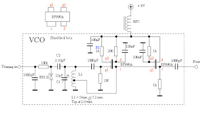
The RF Oscillator is based on a Hartley oscillator. The frequency is determined by L1 and capacitor C1. The Vtuning voltage will change the capacitance in the varactor BB132 wich will change the oscillation-frequency. The value of capacitor C2 will determine how much the frequency can be changed by the tuning voltage. The larger value the more the frequency will change.

This Oscillator Circuit is based on two dual-gate FET. First FET is a Hartley oscillator where the frequency is determined by the value of L1, C1, C2 and the varicap diod. C2 set the span of the VCO. The second FET is just an amplifier. The gain is less than 1, but the current will be higher and the oscillator will not be loaded. The output amplitud changes depending on the frequency and how many turns there is on L1. By changing the voltage on g2 at FET1 you can set the amplitud. By adding a resistor to ground you will lower the amplitudo.

VCO
In this schematic I have conected g2 to Vcc (through R1) wich will give the highest gain.

VCO have made some test with different coils. The diameter of L1 is the same 7.2mm
but I have changed the turns to 3, 4 and 5. The diagram at the right shows the Amplitudo and the frequency. You can also se the range of this VCO. During the test the varicap was removed so the tuning range is set by C1. The best way to get the oscillator work is to attach a oscilloscope to the output. If the amplitud of the oscillator is low, you must move the tap-point a bit. The best way is to make 3-4 coils with the tap-point at different places and test each coil before you decide wich one you will use. The amplitud from my VCO is about 200mVRMS at 100MHz.


Remember: When you are building oscillator you must keep the wires short and shiled the oscillator! then it will work nice.
read more "70-210 MHz RF Oscillator Circuit"

1W FM Amplifier For Ipod FM Stereo Transmitter

The schematic show you a RF amplifier with very high gain. The feeding RF signal enter C9 to transistor Q1 which has a self biased working point. The gain and working point is set with the two resistors R1 and R2. FB1, C5, C6 works as filter for rejecting RF to power line. Q1 has a gain about 15dBm. The output signal can be found a the collector which then enter a second amplifier stage Q2. This stage also has a self biased working point.


The gain is set by the resistors R3//R4 and R5//R6.


Why do I have 2 parallel resistors like that?
It is because I want to be able to change the gain of the amplifier. On the PCB below you will see that I only have 2 pads for the resistors. When I want to resistors I solder the two resistors R5 and R6 on top of each other and the same with R3 and R4.

I advice you to start building without R3 and R5 and test the unit. If you want you can then add R3 and R5 later to obtain max gain of this stage.
Q2 has a gain of 12 dBm. FB2, C7, C8 works as filter for rejecting RF to power line.

The last amplifier stage is based around the transistor 2N3866. This transistor has low input impedance.


I match it by using 2 capacitors (C11, C12) and the inductor L1 to about 50 ohm. The transistor has an output impedance match, (C13, C14, and L3) to get best performance for an 50-75 ohm antenna.

- The inductor L1 is made by a wire 2 turns with 5mm diameter.
- The inductor L2 is made by a wire 7-9 turns with 6.5mm diameter.
- The inductor L3 is made by a wire 4 turns with 6.5mm diameter.

L4 is a Axial Lead Bead, which reject RF very good and has low resistance. You can use almost any choke or large inductor for L4, it is not a critical component.
The FM transmitter require 2 AAA batteries and consume about 38mA.
To get rid of batteries, I have added a voltage regulator IC1, to the PCB which deliver 3.3V to the FM transmitter unit.

The PCB is mirrored because the printed side should be faced down the board during UV exposure.
To the right you will find a pic showing the assembly of all components on the same board.
This is how the real board should look when you are going to solder the components.
It is a board made for surface mounted components, so the copper is on the top layer.


Grey area is copper and each component is draw in different colours all to make it easy to identify for you. The scale of the pdf is 1:1 and the picture at right is magnified with 4 times.

Download PCB mirror, Schematic-Component Mounted Visit Page
read more "1W FM Amplifier For Ipod FM Stereo Transmitter"