Friday, July 27, 2012

QRP operating at Myre-Big Lake State Park


This last weekend Beth and I took our camper trailer to Myre-Big Lake State Park near Albert Lea, MN. I had along my K1 and Crappie Pole 20 mtr C-Pole vertical.

As expected the C-Pole antenna worked well. Over the weekend I had 11 contacts including WA3SLN (PA), K4SPO (KY), K3WWP (PA), AF4O (TN), WB2PEF (NY), VA3RKM (ONT), WB6OJB (CA),WB4KLI (KY), WD9F (IL), W2IQK (NY) and W9LD (WA). I also started a QSO with AB7KT (NV) but that QSO was as victim of QSB/QRM/QRN.

Charles, K1ETU, from Oneonta, NY, spotted me and stopped by for an enjoyable "eyeball QSO". Bill, a camper from Louisville, KY, also stopped by bringing his two sons. Bill has been interested in ham radio since a teenager but had never gotten a license. Now he's thinking of locating a Louisville Radio Club and working on getting his ticket.

The crappie pole frame for my C-Pole really stands out in a campground. It looks like some sort of tall skinny game target or goal. Lots of campers noticed it as they walked or drove by, some asked about it. My favorite comment: "I've never seen a camping accessory like that before".
read more "QRP operating at Myre-Big Lake State Park"

Tuesday, July 24, 2012

Frequency Converter 2.4 GHz to 700 MHz

It's theoretically possible to convert a 2.4 GHz wireless LAN signal to a much lower frequency to help overcome non line-of-sight issues. Many UHF television frequencies in some areas are currenty unused. Those would be great to hijack. You could then use common directional UHF TV antennas for your links. This current design is theory only.

It might even be possible to hack the local oscillator out of an old 2.5 GHz MMDS down converter and use that to drive an external frequency converter.


This might help overcome non line-of-sight issues most people are facing today. Fairly high antenna gain and RF output power should reduce the multipath conditions which degrade wireless data links.

The theory is to mix 802.11b channel 9 (2451 MHz) with a local oscillator frequency of 1536 MHz. The resulting IF frequency is 915 MHz, which is the new transmit/receive frequency. You then will do a little dance to the Gods to keep pagers and cellphones from destroying all your hard work.

The actual bandwith of the RF signal of the final direct sequence spread spectrum signal is 22 MHz wide, between 904 and 926 MHz - centered at 915 MHz.

You should also lower the data rate, say to 1 Mbps, this reduces the TX/RX switching times a bit.

It might also be possible to transvert down to the unused 600 to 700 MHz UHF TV frequencies. You could use those cheap, high gain UHF TV antennas and scrap cable TV hardline.

This design is for reference only, it hasn't been built completely yet. There are several quirks that will need to be worked out: the use of resistive isolation pads at various points, diplexer on the mixer's IF output, PLL loop filter values, and various switching voltages. It can be used as a start to the TAPR Summer 2003 PSR callout for 802.11b transverters.

Since in most urban areas the 900 MHz band is actual worse than the 2.4 GHz band in terms of interference, it may be possible to use this as an IF rig for lowering long coax losses, or even further transverting to the 440 or 1.2 GHz bands.

Source: 2.4 GHz to 700 MHz Converter
read more "Frequency Converter 2.4 GHz to 700 MHz"

Designing RF Filter Faster

How to design RF Filter Fast? A Windows® electrical filter design and analysis program designed to expedite the design of lowpass and highpass filters using Standard Value Components (nearest-5% values). You can view your spectrum analysis filter design.

SVCfilter™ is a program designed to expedite the design and analysis of lowpass (and highpass) filters with nearest 5% component values.


Here are some pertinent features:
  • SVCfilter is 32-bit Windows® electrical filter design software nicely written to help the radio amateur, technician or engineer design and analyze lumped-element lowpass and highpass filters.
  • Order, topology and family are all entered by clicking on buttons.
  • If the Chebycheff or Cauer family is chosen then three options for passband ripple (.01, .044 and .200) are available.
  • If the Cauer family is chosen then four options for stopband depth (30, 40, 50 and 60 dB) are available.
  • Cutoff frequency is entered in the usual text box and can be from audio through UHF.
  • Cutoff frequency can be as low as 0.1 Hz, allowing the value of .159155 [ i.e., 1/(2*PI) ] to be used. This, in conjunction with a termination value of one ohm, yields parts values for the textbook classic "normalized" design.
  • System impedance by default is 50 ohms but a textbox allows entry of any value of your choice, for example 600 ohms for audio.
  • Inductor Q values are set by default to a value of one million. A textbox allows entry of any value of your choice in the range of 10 minimum to one million maximum.
  • The graphic output draws the schematic of the filter you have designed, and also plots the responses of that filter (both transmission and reflection). It selects the nearest 5% values for the capacitors and shows those values as well as the exact values and overlays the response plots for the nearest values on top of the original exact-value plot.
  • Tuning buttons allow stepping the cutoff frequency up or down in 1% steps and immediately seeing the new performance of the redesigned filter on the plot.
  • Place the cursor anywhere on the plot and see the transmission, reflection, VSWR and envelope delay values for that frequency.
  • Inductors are retuned as necessary to maintain the response of Cauer filters after nearest capacitors are chosen.
  • To maintain the high level of quality of the graphic output, the outputs to the printer are not "screen dumps" but instead are from a set of dedicated routines which write directly to the printer. The quality of the graphics as delivered by the printer will be limited only by that printer, commonly several hundred pixels per inch. The printer output on one sheet contains the schematic with parts values along with the set of responses.
  • Click on the "Write Elsie File" button to write a file to drive Elsie the filter design and analysis program for followup filter examination in even greater detail.
  • Click on the "Write Spice schematic" button to write a file to drive the LTspice simulator. (Tonne Software has no connection with Linear Technology Corporation.)
  • This program was written to simplify the sometimes difficult task of lumped-element lowpass (and highpass) filter design by automating or setting as default some of the more frequently-encountered options. But it also includes analysis, uncommon for such an application.

Download SVCFilter - How To Design RF Filter Faster in detail

Source: How To Design RF Filter Faster
read more "Designing RF Filter Faster"

RF Test Probe

Like the Classic RF Probe, this RF test probe is used in conjunction with a high-impedance-input Voltmeter or Digital Voltmeter Meter (DVM). What makes this probe unique is?

What makes this probe unique is that it's built inside the shell of a regular ol' ballpoint pen. Besides being conveniently compact, the unit sports a needle-probe suitable for use in probing surface-mount circuits, and good overall shielding. The pen cap protects the needle probe when not in use.


When measuring sinusoidal signals, it should provide RMS-corrected readings, using a 10 or 11-Meg input impedance VTVM or DVM. With a 1-Meg DVM, it reads 25% of the sinusoidal RMS voltage. Reasonable accuracy (+/- 10%) can be expected over the HF/VHF range (2-150 MHz), although this hasn't been verified. When used to measure non-sinusoidal signals, the accuracy will be unknown, but it still affords good relative measurements, and most of the time, that's all that's required. It makes an excellent, compact, and portable accessory for troubleshooting or homebrewing QRP equipment with peak voltages less than 50 Volts (most solid-state equipment)

RF Test Probe Construction
The figure below shows the parts required to build the Ballpoint RF Probe. Click on the image to open an larger, annotated image with parts labled, and construction notes. Pick a ballpoint pen with a non-metalized plastic body, and plenty of room inside. The Papermate Flexgrip model I used had an inside diameter a little over 1/4-inch. We'll use an itty-bitty scrap of double-sided printed-circuit-board to mount the electronic components. Trim the PC board to about 2-12" long and 3/16" wide; don't make it too wide, or it won't fit inside the ballpoint pen. Notch or file a little out of the middle of the pc board, so the 1N34A diode will fit easily inside the pen body. then, on one side only, groove in two places, so as to create 3 lands on the "top" side of the board.


In addition to the rf test probe parts shown, you'll need a 2-1/2" piece of heat-shrinkable tubing to cover the electronic assembly (although electrical tape would do instead), and about a foot of 1/4"-wide adhesive-backed copper tape, commonly available in rolls of 200-300 inches at large hobby stores. Although a chip capacitor is shown in the photo, a very small disc capacitor will do as well.

Source: N5ESE's Ballpoint RF Probe
read more "RF Test Probe"

Monday, July 23, 2012

Just back from Rhine trip

Some interesting post whilst away...

Seems I came 2nd in IOTA qrp category in EU005 during 2009 as I have a certificate!

Lots of QSl cards some go back as far as 2006, lots more 3B8/M1KTA.

An FPGA development board.

Anyway I'll be preping for the RSGB IOTA contest later and making a 12 our entry again then back to melting solder on the MOBO builds.
read more "Just back from Rhine trip"

Saturday, July 14, 2012

MP3 FM Transmitter Circuit

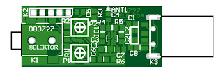
Here's a simple VHF FM transmitter that could be used to play audio files from an MP3 player or computer on a standard VHF FM radio. The circuit use no coils that have to be wound. This FM transmitter can be used to listen to your own music throughout your home. When this FM transmitter used in the car, there is no need for a separate input to the car stereo to play back the music files from your MP3 player.

To keep the circuit simple as well as compact, it was decided to use a chip made by Maxim Integrated Products, the MAX2606 [1]. This IC from the MAX2605-MAX2609 series has been specifically designed for low-noise RF applications with a fixed frequency. The VCO (Voltage Controlled Oscillator) in this IC uses a Colpitts oscillator circuit. The variable-capacitance (varicap) diode and feedback capacitors
for the tuning have also been integrated on this chip, so that you only need an external inductor to fix the central oscillator frequency.


It is possible to fine-tune the frequency by varying the voltage to the varicap. Not much is demanded of the inductor, a type with a relatively low Q factor (35 to 40) is sufficient according to Maxim. The supply voltage to the IC should be between 2.7 and 5.5 V, the current consumption is between 2 and 4 mA. With values like these it seemed a good idea to supply the circuit with power from a USB port.

A common-mode choke is connected in series with the USB connections in order to avoid interference between the circuit and the PC supply. There is not much else to the circuit. The stereo signal connected to K1 is combined via R1 and R2 and is then passed via volume control P1 to the Tune input of IC1, where it causes the carrier wave to be frequency modulated. Filter R6/C7 is used to restrict the bandwidth of the audio signal. The setting of the frequency (across the whole VHF FM broadcast band) is done with P2, which is connected to the 5 V supply voltage.

The PCB designed uses resistors and capacitors with 0805 SMD packaging. The size of the board is only 41.2 x 17.9 mm, which is practically dongle-sized. For the aerial an almost straight copper track has been placed at the edge of the board. In practice we achieved a range of about 6 metres (18 feet) with this. There is also room for a 5-way SIL header on the board. Here we find the inputs to the 3.5 mm jack plug, the input to P1 and the supply voltage. The latter permits the circuit to be powered independently from the mains supply, via for example three AA batteries or a Lithium button cell. Inductor L1 in the prototype is a type made by Murata that has a fairly high Q factor: minimum 60 at 100 MHz.


Take care when you solder filter choke L2, since the connections on both sides are very close together. The supply voltage is connected to this, so make sure that you don’t short out the USB supply! Use a resistance meter to check that there is no short between the two supply connectors before connecting the circuit to a USB port on a computer or to the batteries.

P1 has the opposite effect to what you would expect (clockwise reduces the volume), because this made the board layout much easier. The deviation and audio bandwidth varies with the setting of P1. The maximum sensitivity of the audio input is fairly large. With P1 set to its maximum level, a stereo input of 10 mVrms is sufficient for the sound on the radio to remain clear. This also depends on the setting of the VCO. With a higher tuning voltage the input signal may be almost twice as large (see VCO tuning curve in the data sheet). Above that level some audible distortion becomes apparent. If the attenuation can’t be easily set by P1, you can increase the values of R1 and R2 without any problems.

Measurements with an RF analyzer showed that the third harmonic had a strong presence in the transmitted spectrum (about 10 dB below the fundamental frequency). This should really have been much lower. With a low-impedance source connected to both inputs the bandwidth varies from 13.1 kHz (P1 at maximum) to 57 kHz (with the wiper of P1 set to 1/10).

In this circuit the pre-emphasis of the input is missing. Radios in Europe have a built-in de-emphasis network of 50 μs (75 μs in the US). The sound from the radio will therefore sound noticeably muffled. To correct this, and also to stop a stereo receiver from mistakenly reacting to a 19 kHz component in the audio signal, an enhancement circuit Is published elsewhere in this issue (Pre-emphasis for FM Transmitter, also with a PCB). Author: Mathieu Coustans, Elektor Magazine, 2009

MP3 FM Transmitter Parts List
Resistors (all SMD 0805)
R1,R2 = 22kΩ
R3 = 4kΩ7
R4,R5 = 1kΩ
R6 = 270Ω
P1 = 10kΩ preset, SMD (TS53YJ103MR10 Vishay Sfernice, Farnell # 1557933)
P2 = 100kΩ preset, SMD(TS53YJ104MR10 Vishay Sfernice, Farnell # 1557934)
Capacitors (all SMD 0805)
C1,C2,C5 = 4μF7 10V
C3,C8 = 100nF
C4,C7 = 2nF2
C6 = 470nF
Inductors
L1 = 390nF, SMD 1206 (LQH31HNR39K03L Murata, Farnell # 1515418)
L2 = 2200Ω @ 100MHz, SMD, common-mode choke, 1206 type(DLW31SN222SQ2L Murata, Farnell #1515599)
Semiconductors
IC1 = MAX2606EUT+, SMD SOT23-6 (Maxim Integrated Products)
Miscellaneous
K1 = 3.5mm stereo audio jack SMD (SJ1-3513-SMT
CUI Inc, DIGI-Key # CP1-3513SJCT-ND)
K2 = 5-pin header (only required in combination with 090305-I pre-emphasis circuit)
K3 = USB connector type A, SMD (2410 07 Lumberg, Farnell # 1308875)

Notice. The use of a VHF FM transmitter, even a low power device like the one described here, is subject to radio regulations and may not be legal in all countries.
read more "MP3 FM Transmitter Circuit"

Monday, July 2, 2012

Real Radio?


Yeah, it glow!
Real Radio Glow In Dark!


Breadboarding the new T.N.T. based transmitter design. Coming soon.
read more "Real Radio?"