Yesterday was the Winter 2011 Classic Exchange. This event offers a great chance to get on the air with older gear. Participants putting multiple vintage transmitters and receivers on the air have a big score advantage, but it's fine to put only one vintage station on the air or work others using, even, a software defined Flex-5000A.
This year, after going through the possibilities, I settled on five stations I'd like to have in the CX:
In all I made 11 contacts (but only 10 counted for points) and I used 4 of my 5 stations. The CX gave me a chance to play with a couple of radios I haven't used in a while and to fine tune a little what I'm looking for in my favorite "boat anchor" station.
New Item Dual 20pf and 335pf Poly Variable Capacitors.
These can be connected in a number of different ways. You can have a dual 16pf to 371pf from this one capacitor. For wiring connections and the possible combinations go to my website.
Following on from my last post it seems I have found the main source of QRM that was caused by one of my PCs at least. In the pic with my previous post you may have noticed the "Black box" Icom PCR1000 receiver, sitting on top of my little HF linear amp. That receiver is connected to the main pc-the one I have moved onto another desk.Having moved that PC I found that the S9 of noise on 10 metres which was always there when the PC was on had disappeared. Today I decided to reconnect the Icom receiver. Since the Icom uses a serial port connector I use a USB to Serial lead out of the PC which connects to serial lead and then to the Icom. Plugging the lead into my USB hub, Windows 7 automatically installed the USB to serial driver and then............S9 of noise on 10 meters. Moving the lead directly into a USB on the PC reduced this to S6 but unplugging altogether reduced the noise to nil. I don't know why this lead should be radiating noise like this, but I will try and move the Icom receiver to be controlled by the other PC. Perhaps winding the lead around a ferrite ring would help? I think I have one here and will give it a try.If that doesn't work I think I will be moving the Icom on.
I managed to find a space to reinstall the Trio/Kenwood TS830s on the Desk. Now all I need is a three way switch so I can switch my antenna between the three HF rigs. Whilst I was about it I moved the main PC further away from the radios. This has greatly reduced the QRM I was getting from that PC. The older PC which I use for PSK31 still generates some noise. In order to move that I will either need to get extension cables for the keyboard and mouse or maybe pick up a wireless mouse and keyboard set.
When I look at all the gear in the picture here it strikes me that the little Yaesu FT857D which you can see on top of my Yaesu FT1000MP could in fact do everything that all of the other gear could do, all in one tiny box. At present I just use the 857 on VHF. Perhaps I should clear the decks and use a minimalist shack based around the 857? :-)
Dave Farrell purchased my Crystal Radio Kit CRK-1 for his class on Crystal Radios. He said the kids loved them. He made a powerpoint presenation outlining the class. He also has some theory on how a Crystal Radio Works.
I don't really want to appear to be a "doom and gloom merchant", but a chance series of events caused me to learn that we (shortwave listeners) are about to lose another source of programming on shortwave, that of the very well known and respected "Radio Prague".
The sequence of events to which I refer started with the fitting of a 6kHz AM filter to one of my "classic" old transceivers, my FT-107M.
The filter was acquired from a fellow amateur who had acquired an FT-101ZD complete with said filter, but who wanted to return it to its "factory condition". For those not in the know, the FT-101ZD though equipped with AM facilities (a special board had to be acquired) had a rather lame implementation of this mode due to the way the "IF Shift" was connected (long story). The bottom line of this tale was that this particular FT-101ZD owner and myself eventually figured out what the previous owner had done and the modification was successfully undone, and the grateful new owner awarded me the unwanted AM filter as my reward!
This was a mutually acceptable arrangement, and today was the day I decided I would fit this filter to my FT-107M, as that particular radio implements the AM mode "properly".
The fitting of the filter to this radio was simplicity itself, and when it was done I decided to have a little tune around the 7MHz, or "41 metre" band looking for broadcast signals.
In early morning there is no shortage of strong signals from Europe, and before long I found myself listening to Radio Prague on 7.345MHz for the umpteenth time in my life.
As is usual these days shortly before the radio station closed down its English broadcast the announcer gave out some information about how to find Radio Prague on the Web (www.radio.cz), and a few minutes later I surfed into that very web site, like one does.
To my dismay my eyes alighted straight away onto a piece entitled "Radio Prague's shortwave broadcasting to end on January 31, 2011", the content of the article citing budget cuts as the reason why.
Now, the economics of shortwave broadcasting are a subject not unknown to me, as earlier in my life I worked in this medium, and was familiar enough with costs due to the fact that I actually signed cheques payable to the Regional Electricity Company who supplied the power to a major shortwave broadcasting station! Been there, done that, got the T-shirt ...
What I could never really relate to was the "value" in such broadcasting, as, being a Brit, I only ever was a "hobby" consumer of this medium. I was always told that overseas things were very different, and the average man-in-the street relied on shortwave to bring him news just as much, if not more so as he relied on his daily newspaper. I am sure this has been very true, but I wonder whether it is still true. I strongly suspect that it isn't, generally speaking, and, logically, many other broadcasting stations will soon be going the way of Radio Prague.
I would say, therefore, "enjoy them while you can" !
For the last couple of days I have been using the CW GET software to help practice my CW sending. Although it can be quite distressing to see thaT what you thought was good CW isn't. CW GET is not like the human ear. It doesn't make any allowances. If your timing is slightly out your G will appear on CW GET as a T and an N and so on. One thing is for sure when I do go on air for my first (for 20 years) CW I will use my straight key rather than the paddle- results were a bit better with that! More practice needed on the paddle I think!
Just downloaded and installed the JT65a software I have been reading so much about. It looks really complex! I have also been reading a handy guide to this mode "The Complete Bozo's Guide to HF JT65A ( a work in progress)"by Andy K3UK. I'm not sure I will get the hang of this mode but will try monitoring first to see how I get on. In the meantime I have also been playing around with the Flidgi software and managed to decode an MFSK16 transmission with it today. I have been using Digipan for years on PSK31, I can see Flidgi is a more versatile piece of software but I think it will take me a while to get used to the user interface.
Project group ok'd it so I'll add ExpressPCB layouts for the PCB on the yahoo group as I create them. Please be warned check them before you use them and needless to say if you see an issue please advise.
Had a great day today! Finally used my Arduino camera controller for something useful - making a timelapse photo of our photo society's portrait session
Those who have seen my QRZ.com entry will know that I have been planning to resurrect my old G8 call. This has now happened, the paperwork arriving today. So I am now the proud owner of TWO UK callsigns!
It's a wee bit curious why as to why this is permitted, and though I tell myself I am not one to covet another man's possessions, when I learned some while ago that some of my radio friends were in possession of both their old class B callsign and their more recent one, I felt I had to join this particular club.
I have had one or two arguments with folk who say they were told upon upgrading their licence when they achieved the Holy Grail of the 12 wpm morse test, or whatever, that they could NOT keep their old callsign.
However, the current regulations allow for (and this is quite clear from the text of the current Amateur Licence Application Form OF346) that a LAPSED licence (Class "A" or Class "B") previously issued to the applicant can be reissued upon production of certain documentary evidence that the applicant did at one time hold that callsign.
This latter condition wasn't too difficult for one such as myself who hardly ever throws anything away, and faded correspondence between myself and the then regulatory body (Home Office) was scanned and reprinted, catalogued with a covering explanatory letter and compiled into a dossier complete with OF346 filled in, and hey presto, two weeks later G8LBT was reborn!
I'm still not quite sure why I did it! Maybe it rolls off the morse key a little more nicely than my G4 one?
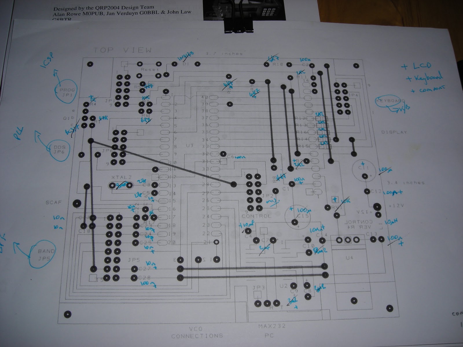
I was asked if an electronic version of the PCB masks exist for the project. They don't and as I like using it I have started to create Express PCB versions of the PCB. This is the control board. Note I have used the NARROW SOIC-16 version of the MAX232/ST232 SMD I will also consider the normal DIL version too.
The layout are sized exactly the same as the originals and generally will follow the original layouts, right now no bottom layer tracks exist on this image on the blog.
I'll work through all the boards and possibly build up an alternative making a few additions, I may produce a layout using SMD components where possible for many of the discrete components especially the R and C.
Note I do not create the .sch files just the .pcb files.
I'll wait to hear from the project group if they mind these being shared.
Same as above in poor French: Le même que ci-dessus en français pauvres. Apologie de langue maternelle française.
On m'a demandé si une version électronique des masques PCB existent pour le projet. Ils ne sont pas et que je veux l'utiliser, j'ai commencé à créer des versions Express PCB de la carte. C'est le tableau de commande. Remarque, j'ai utilisé le ETROIT SOIC-16 version de la MAX232/ST232 SMD Je vais également examiner la version DIL normal aussi. La mise en page sont exactement les mêmes dimensions que les originaux et en général suivront la mise en page originale, à l'heure actuelle aucune piste couche de fond existent sur cette image sur le blog. Je vais travailler par tous les conseils et peut-être constituer une alternative faire quelques ajouts, je peux réaliser une maquette en utilisant des composants SMD, si possible pour de nombreux composants discrets en particulier la R et C. Note Je ne crée pas les fichiers sch. Seulement les fichiers de pcb.. Je vais attendre d'entendre le groupe de projet si elles l'esprit ces partagé.
The motivation After seeing Matt Richardson's video about his high-speed photography controller, I thought to myself "Wow, I want one of those!" And I had all the necessary bits, so I set about building one.
This post isn't going to be a how-to (I'll write one if enough people offer to buy me beer), but just general boasting about what it does.
What can it do?
Ok, so I now have a device which can trigger my camera's shutter, fire off a flashgun or turn a bunch of sockets on and off at my command. Just think of the possibilities!! It's basically up to me and what program I write.
Taking Matt's lead, I first created a program to take photos of popping balloons. Here's a rough outline of the process:
Start the process (by pressing a button)
Arduino turns room lights off (via a relay attached to an extension lead)
Camera shutter opens
Arduino waits for sound of balloon popping
I stick a pointy thing in a balloon
Arduino hears the sound, and fires off the external flash unit
Camera shutter closes
Room lights turn on
Paddy has a beer to celebrate a successful day's work
For an explaination of the above, see my next post (LINK COMING SOON). For some results, see my Flickr Arduino tag
I've also created a timelapse Arduino program, which allows me to repeatedly take photos a certain number of seconds apart - I created a simple video of a candle burning away, seen below
The parts
What I've used (essential stuff)
1x Arduino Pro (though most Arduinos are suitable)
1x Quad opto-isolator
1x 7d remote trigger (sabbotaged for its connector and cable) - A cheap knock-off one was ideal because it cost about £5 ($8)
Various pieces of stripboard
Various colours of wire - For wiring up the circuit, but I also used a lot to make the tails to go off to the external stuff like the flash and camera
Non-essential stuff (added for the cool factor)
Real time clock module - allowing for more accurate timelapses
Lots of male and female PCB pin headers - these make up the plugs for wires, or the slots to plug the Arduino in so it can be removed easily
4x LEDs (various colours) to show the status
2x PCB-mount buttons to set the functions
Transistors - Arduino can't source enough current to power LEDs itself (though I'm told it can sink it - can any confirm?)
Piezo transducer - to pick up loud sounds
Photodiode - to pick up the light from a laser pointer (laser tripwire!)
Various resistors - they're boring, but ya need 'em
Stuff I didn't add (but would love to)
LCD status screen
Ion cannon - not really essential for this project, but how cool would it be if you could take photos and then blow stuff up?
Some requirements I aimed for Functionality:
Control the camera focus and shutter (obviously) - the "how" is discussed below
Control an external flash gun - also discussed below
Two buttons to program the device - so I don't have to download a new program every time I want to change between "take picture when lights are bright" and "take picture when lights are dark" modes, for example
4 LEDs to display the status - in the end only 3 of mine worked, but it's still plenty
Expandability:
Inputs and outputs should be as generic as possible This wasn't always possible (i.e. for the camera connector) but where I could, I tried to make the inputs and outputs generic. For example, the relay to switch the sockets on and off is on a separate piece of stripboard, and just plugs into a simple digital out. This means I can design as many little plugins as I can think of and still use the same main board
Input buttons have ports to plug external buttons in (so I can carry a button around with me, instead of having to be right beside the controller)
Camera Control The camera (in this case a Canon EOS 7d) is controlled via the cable from a remote shutter release (about £5 on Amazon). These shutter releases (at least for Canon) are just simple switches. There are three wires in the cable - ground, focus and shutter. Connect focus to ground, the camera enters "focus" mode (like half-pressing your shutter button). Connect shutter to ground... well you get the idea.
In order to isolate my very expensive and love-of-my-life camera from my shoddy soldering, I used an opto-isolator. These little devices look like a standard IC chip, and basically consist of an LED on one side, and a photo-diode on the other. Apply a voltage to the input side, LED lights up, photo-diode allows a current through on the other side. You'll notice that there is no direct electrical connection between the input and output side - there's no need to worry about frying your camera if you short something out on the other side of the isolator, it provides about 7,500V of electrical isolation (or so the datasheet says).
Flash Control I needed to be able to control an external flash to really get that "motion-stopping" effect. I have two external flashguns - a YN-460 and YN-468. The trigger for both of these is a hotshoe, which means the flashgun provides a 6V voltage on the center pin, and when this is brough to ground (via another contact around the edge of the shoe), the flash will fire. This sounds like another job for an opto-isolator!
To make things easier for me (and because I don't have any hotshoe adapters) I added a small homemade sync port, which you can read about here
External lighting control This was such a good idea from Matt's video that I couldn't not do it!
Matt had a fancy extension lead with a digital input for turning it off and on. I don't have such crazy technology, so I had to make one myself.
What you see above is a small piece of stripboard, with relay which opens or closes based on a digital signal it receives from the Arduino. I've cut the live wire in a 4-way extension lead, and inserted the relay in the gap.
There's a little bit of circuitry so that the low current 5v output signal from the Arduino can power a 12v relay coil, but other than that it's very simple.
Because this board needs 12v, I usually power it directly, and I've added a socket so I can take power from this board and take it to my main board (which has the Arduino). The main board has an onboard regulator to give me 5v.
Inputs In this iteration there are 4 (3?) inputs - two buttons and a socket for a photodiode. I know I'd said I was trying to keep everything generic, but I didn't have the awesome idea of having additional bits of stripboard with extra circuitry at that stage.
One of the buttons also has a socket, so that I can plug an external button with a long wire on it. This gives me freedom to move around the scene, makeing life so much easier!
There's room for other inputs too, and another socket for an opto-isolator, but I haven't got round to doing the wiring yet.
Arduino Code This is coming in my next blog post. [INSERT LINK HERE]
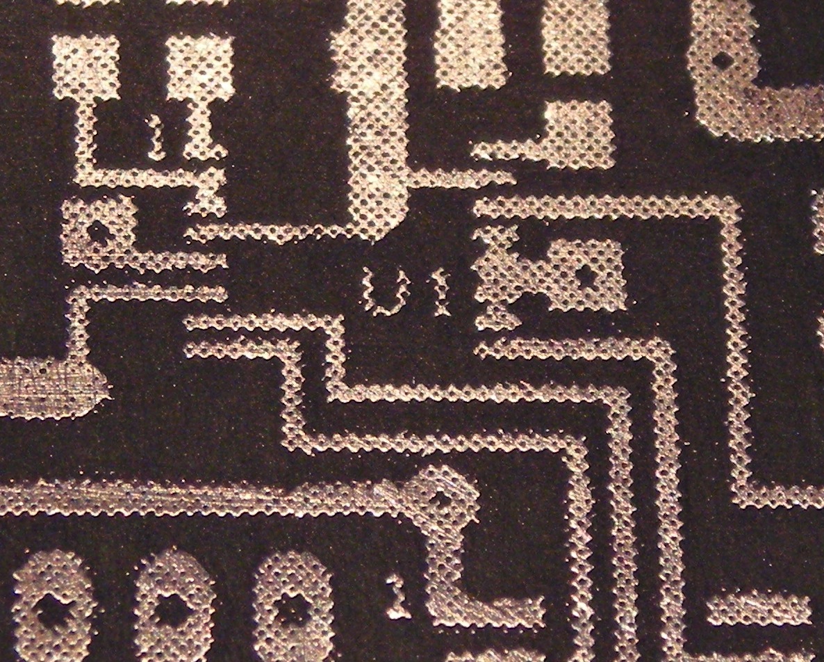
The prepared Control PCB is fitted with all the IDC sockets and wire links including all the wire links through the board so the ground plane is connected both sides. In the above photograph you can see I have prepaced some of the components before continuing. On the reverse side there are just two wire links, 5 2K2 SMD resisors and the ST232 SOP SMD IC. Note if you are going to use the project group PCB masks you need to use the ST232CWR WIDE body version.
I am building from one of the component sets I previously put together, I printed off a copy of the yahoo group spreadsheet to mark off the components. I have a number of bags that I have presorted the components into according to the boards.
The LCD connections to the Control Board I have used a SIL connection strip and it is connected to the LCD by a length of ribbon cable. The 7805 regulator will need mounting hardware as well.
Apropos of nothing, today I received one of the occasional EMails I get say that there was an "eQSL" awaiting me at www.eqsl.cc.
When I logged in I was greeted with the news that my membership had been "downgraded" (in other words I hadn't made a financial contribution for over a year), so I duly fired up the PayPal screen and bunged them a few quid, as I have always thought that this service has been worth supporting. No big deal.
However this prompted a mental process which recalled all the "please no eqsl" messages I had seen scrolling across the screen whilst operating PSK modes, and I thought to myself "Why the heck not?".
It's completely understandable view from someone who has no PC or internet connection, but my experience is that the vast majority of hams across the world are now connected to the 'net, and therefore by definition (almost) must have a PC available to assist them in their hobby. Certainly virtually every PSK operator has a PC, as that is how that mode usually operates!
I realise that there are "issues" with eQSL not being "acceptable for awards", probably due to "authenticity" issues, (from the point of view of one who _doesn't_ chase awards), but on the whole I find it a splendid service; easy to use, inexpensive (you can use the system completely FREE OF CHARGE if you wish, albeit with some limitations in functionality, which I think is a pretty fair deal), and reliable (I can't recall any service outages over the period I have been using it).
The "accepted" alternative is the ARRL's LotW (Logbook of the World), which, apparently addresses the "authenticity" issues, but which is an absolute pain-in-the-arse to use (IMHO), and doesn't produce any kind of "QSL card" which eQSL does. When my LotW account needed revalidating recently, I had a heck of a job remembering and working out just how I was supposed do do it, and although I got there in the end, I was almost on the point of giving up before I hit on the correct combination of actions.
Some hams like to plaster their shack walls, or fill shoeboxes with pieces of cardboard commemorating contacts - I'm not included in this list, being perfectly happy to have a line in a logbook, or an electronic record such as eQSL.cc provides, and I accept that it "takes all sorts", but "PSE NO EQSL" does seem to be a "dog in a manger" attitude to me!
One QRZ.com entry I came across the other day stated that paper QSL cards were "honourable", and implying therefore the eQSLs were not. I think you can tell that I do not share this opinion.
As part of a larger project today I needed to sync my flashgun with an Arduino. Since I don't have any hotshoe connectors or anything like that, I decided to add a sync port to the flash itself.
Now I've read more than a few posts about people adding PC sync ports to their flashes (especially the YN-46x series), but since I don't own a single PC sync cable or any kind of connectors, I decided to go with a more breadboard/Arduino friendly option.
This hack doesn't impare the function of the flashgun in any way - it still functions as a normal flashgun, via the hotshoe or optical slave. It's just got an extra connector.
What you see above is the finished product - the addition is just a tiny 2-pin PCB header, like the ones you get on the Arduino itself. It's cheap, tiny and versatile, and it fits right into the base of the unit.
And that's the inside of the base. I've simply drilled a few 3mm holes in the side, cleaned up the hole with a knife, and slid the connector in.
The connector (seen above right) is 2.56mm pitch female PCB header (the big black strip). It comes in rows of 20 and needs to be cut to size. You can do this with a knife (carefully, and on a cutting mat!). It's pretty cheap on eBay, which is good, because I go through stacks of it!
Once I had the hole drilled and the connector slid in place, I soldered from the terminals on the new connector to the terminals on the existing connector. Finally, I covered the whole thing in Uhu glue to keep it secure (I forgot that the centre pin moves up and down - DON'T PUT GLUE ON THE CENTER PIN)
What I have now is a flashgun which can be hooked up to a breadboard for use with an Arduino. To trigger the flash, simply join the two leads together (either physically, with a physical switch, or with some kind of electronic switch)
Check out my next blog post (still to be written) to see what you can achieve with a Canon 7d, flashgun, Arduino, laser, and things which will break or pop or explode
First post in a loooooong time! I've since picked up a new hobby, so you're going to be seeing a lot of posts about photography!
It's a well known fact that using a longer focal length lens, and then stepping backwards so you can still fit your subject in frame, will "compress" the perspective in your image (i.e. make background objects appear a lot closer to your foreground).
What I haven't been able to find out until today was the effect of using different focal lengths, but keeping the same shooting position and cropping the image down to the same field of view. Seems that this has no (or very little) effect on perspective.
Any slight differences in the image above are probably due to the effect of lens distortion (barrelling, pin cushioning), or me forgetting to focus on the same point for each frame.
Images above taken with a Canon EOS 7d (1.6x FOVCF), using a 28mm f/2.8, 50mm f/1.8 and the awesome 70-200mm f/4.0 USM. All shots taken at f/4.0
 In all I made 11 contacts (but only 10 counted for points) and I used 4 of my 5 stations. The CX gave me a chance to play with a couple of radios I haven't used in a while and to fine tune a little what I'm looking for in my favorite "boat anchor" station.
 In all I made 11 contacts (but only 10 counted for points) and I used 4 of my 5 stations. The CX gave me a chance to play with a couple of radios I haven't used in a while and to fine tune a little what I'm looking for in my favorite "boat anchor" station.