Strong signals are few and far between here at the Shady Creek Resort but I'm still been able to make contacts using my K1 running five watts into my Crappie Pole C-Pole antenna.
My surprise contact yesterday was EA6UN on the Balearic Islands off the coast of Spain in the western Mediterranean Sea. That's over 4600 miles on my five watts. I found Jurek calling CQ on 14.050 MHz with no responses. He came right back to me and gave a 579 report. Today's QSOs have all been to the west...WB6HGJ (CA), W7LPV (AZ) and N6IV (CA).
Sunday, June 24, 2012
Friday, June 22, 2012
W0VLZ Operating
I have almost a week to kick back at a lake resort here in north central Minnesota. As usual I have my K1 along. In the past I would have made use of a tree as an antenna support for my end fed 67' wire antenna. This time I'm using my  Crappie Pole C-Pole antenna.
Conditions have been marginal at best with strong signals few and far between and QSB the order of the day. Daily operating has been rewarded by a few contacts....VE3FIT (Toronto, ON), N3EIN (Coatesville, PA) and
W9FHA (Evansville, IN). Another contact, with K9WWT in Merrillville, IN, was a victim of QSB. My signal went from 589 to unreadable in the length of George's initial transmission.
 Crappie Pole C-Pole antenna.
Conditions have been marginal at best with strong signals few and far between and QSB the order of the day. Daily operating has been rewarded by a few contacts....VE3FIT (Toronto, ON), N3EIN (Coatesville, PA) and
W9FHA (Evansville, IN). Another contact, with K9WWT in Merrillville, IN, was a victim of QSB. My signal went from 589 to unreadable in the length of George's initial transmission.
Thursday, June 14, 2012
MOBO V4.3.4 SR V6.3 (Original) preparation

I just build a new SR V6.3 from scratch and added the headers for RX and TX IQ and beefed up the power.
I didn't have a 1N5422 but I have a 1N5408 instead and after a quick test then extended the diode PCB pads a little so not as 'tidy' as the little DO41 drop in replacement.

I did a scratch rebuild as the previous build had a LDVS version not a CMOS Si570 in place as a sample chip and could go to >260MHz and as this is for SDR-Radio development I will keep the build to 'vanilla' only.
I noted the MOBO kit seems to have plenty of jumper connectors so will make some up.
I will use a length of RG174 or similar for the RF and I will use some shielded audio cables for the RX & TX IQ.
Wednesday, June 13, 2012
MOBO V4.3.4 POWER SWR Head


Images of the build.
I used a length of RG58 as the single turns through the binocular core.
I will also homebrew one of these using 1N5711 and discrete components.
MOBO V4.3.4 Mini Filter A Set


PCB made up and installed.
Quick test on a VNA shows the filters frequencies are about right.
MOBO V4.3.4 PA


I did this:
MOSFET attaches to REAR.
I used a needle file and removed the anodising on the bottom ends of the heatsink and around the TO220 middle mounting hole.
To attach th heatsink to the PCB I used two self threading M3 (ish) screws that bit into the heatsinks and created a good contact (I checked resistance was <0.1ohms). Turned the board up away from you on the right hand side (R30) underneath I used a flat washer and a Computer red insulating washer, on the left hand side I used a flat washer and a star washer that bit into the tinned area. In between the heatsink and the top of the PCB on both sides I placed a star washer.
I secured the heatsink to the PCB first THEN and Only after it was secure did I attach the MOSFET and then checked for conductivity between the ground tab on the MOSFET and GND on he PCB. Once satisfied it was good I soldered the MOSFET into place.
The Heatsink sits about 1/32" off the PCB and it and all mounting hardware is clear of any components..
NB on the (outer edge of PCB) of the TO220 mount I used a brass washer and heat sink compound between the MOSFET and the heatsink, The screw was brass M3. On the reserve side (facing into the PCB) no heat sink compound and I used a star washer and flat brass washer to make a good contact between the MOSFET and the heatsink.
Tuesday, June 12, 2012
MOBO V4.3.4 Build for SDR-Radio Support
Asked where I am with this so here are the latest images.
About to add the PA.
Then will build the Mini Filters (Set A).
I have a Blue and White 4x20 LCD and a 36 pulse rotary controller. I have a 128 coming from US but not here yet.
Once all together will test and align... then it will be ready for Simon.


6N7 Tube QRP Power Amplifier - One Rainy Day DIY Project
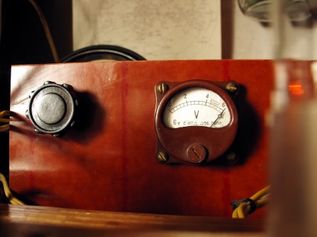
Once upon a time I'd decided to join a Big Guns Gang and made a Super-Duper Powerful Vacuum Tube
QRP amplifier for my 800mW
QRPP homebrew telegraph vacuum tube transceiver "3T"
(I promise to write a separate article or two about this three tube transceiver project later).
It was not an easy decision to me because for that legendary time I'd almost a year used the
QRPP power of less than a watt,
but there was a rainy spring day, I've called CQ again and again without any takers and, at very last,
somebody took over my only rock bound frequency. "That's all" - I said - "Enough!" ..and turned on my Soldering Iron.
Let me describe the scheme. Grounded-Grid design has been chosen because it is simple, easy to matching
to coaxial impedance, provides the necessary level of amplification and typically requires no neutralization.
After several experiments with triodes and double triodes I'd chose a 6N7S (6H7C) valve - Russian glass shaped
version of well known 6N7 vacuum tube. I know that there was a 6N7G and 6N7GT American glass tubes, but as I heard these ones was not as common as metal 6N7.
READ MORE >>
Monday, June 11, 2012
Sunday, June 10, 2012
The Mitey Mite Beginner Transceiver
Last weekend I attended the TwinsLAN/3M swapmeet in St Paul, MN. This is always one of my favorite swapmeets of the year. It is open-air in a large parking lot so all of the boatanchors show up that we don't want to lug inside to a table...just throw open the van doors or uncover the pickup bed and sell.This year I saw many more boat Nationals, Hallicrafters, Johnsons and Heathkits than I've seen in the past...it was a great meet.
One item caught my attention, a late 40's United Surplus Materials "Mity Mite" HF radio. It is a three tube regenerative receiver/transmitter. The audio stage of the two tube receiver doubles as a single tube crystal controlled oscillator/transmitter. The third tube is a rectifier. I bought it from KB0DVM. He built and used this little rig while he was an Ag student at U of Wisconsin/Madison in 1948.
This is a great example of a minimal design making use of available WWII surplus parts. The first steps in the instruction manual explain how the disassemble the included BC-745 pogo stick transceiver tuning unit to get the crystal, two sockets, a tuning coil and the bandset capacitor. The design itself would not make it off of today's drawing boards. First it is an AC-DC set with one side of the AC line connected directly to the metal chassis/cabinet...what a shocker! A safer (and more expensive) AC-DC design has circuit ground isolated from the chassis but not this one. A quick look at the operating instructions shows a note about not connecting an antenna ground but nothing about the shock hazard. Next there is no tuned circuit in the transmitter output. Any harmonics generated by the crystal oscillator are passed unattenuated to the antenna. Again not a good design but it works, though on several bands at the same time.
The Mity Mite is a pretty neat little radio that reflects the time and market it was designed for. It is a keeper. I'll probably figure out a way to put it on the air (while staying on one band and not killing myself).
 up that we don't want to lug inside to a table...just throw open the van doors or uncover the pickup bed and sell.This year I saw many more boat Nationals, Hallicrafters, Johnsons and Heathkits than I've seen in the past...it was a great meet.
One item caught
 my attention, a late 40's United Surplus Materials "Mity Mite" HF radio. It is a three tube regenerative receiver/transmitter. The audio stage of the two tube receiver doubles as a single tube crystal controlled oscillator/transmitter. The third tube is a rectifier. I bought it from KB0DVM. He built and used this little rig while he was an Ag student at U of Wisconsin/Madison in 1948.
This is a great example of a minimal design making use of available WWII surplus parts. The first steps in the instruction manual explain how the disassemble the included BC-745 pogo stick transceiver tuning unit to get the crystal, two sockets, a tuning coil and the bandset capacitor. The design itself would not make it off of today's drawing boards. First it is an AC-DC set with one side of the AC line connected directly to the metal chassis/cabinet...what a shocker! A safer (and more expensive) AC-DC design has circuit ground isolated from the chassis but not this one. A quick look at the operating instructions shows a note about not connecting an antenna ground but nothing about the shock hazard. Next there is no tuned circuit in the transmitter output. Any harmonics generated by the crystal oscillator are passed unattenuated to the antenna. Again not a good design but it works, though on several bands at the same time.
The Mity Mite is a pretty neat little radio that reflects the time and market it was designed for. It is a keeper. I'll probably figure out a way to put it on the air (while staying on one band and not killing myself).
Saturday, June 9, 2012


Tuesday, June 5, 2012


Monday, June 4, 2012
IF/AF Strip

I have been building a few things lately all using a 612/xtal/612/lm386 IF/AF strip so I made a PCB layout for it as I ran out of manhatten pads and the expresspcb software was easy to use. I just reworked it and this was done using Wine under Mint Linux (see W8DIZ latest series of QQ articles). If you really need it ask and I can send you the .pcb file, but I never drew designed or made a schematic file and I tend to use pretty wide tracks and spacings as much of the use is with older salvaged components and I found it easier to solder some things that way.
I have made using single and double sided PCB with blue press n peel film I don't actually send off to Express PCB to make them up.
The layout is for variable band width xtal filter using diodes as variable capacitors (no identification on the layout) but you could omit them and the resistors and an external pot/voltage control and just use fixed value caps instead. I have used MV209, MVAM109 varicaps, 330pf and 560pf caps for the filter. I seem to use 100pF or 220pf for the xtal filter in/out. Xtals are cheap HC49 types I have bags of and I sort of match them crudely (colpitts oscillator) including the BFO. If don't want to use 4 crystals just bridge the ones you do not want to use. Note the BFO one of the capacitors is a trimmer (don't have a component for it sbut I know for me a normal cap pin out works. The L on one leg of the BFO crytsal can be removed, it allows it to be pulled a bit.
The L on the input can be bridged.
I have included dual voltage regulators providing 8V and 6V from a typical 12V source but a 9V source will do just as well. In that case apply 9V to the 12V location, omit the first regulator (right of 12V in) and the electrolytic but use the regulator upper hole and place a 0.047uF or 0.1uF in it to (ground) centre regulator pin hole. I made up with TO220 but the holes also suit TO92 as well (check the component layout for the TO92!).
After fun and games with a QRP ARCI 72 part challenge entry I never managed to submit in the end I altered the PCB and it now includes RX mute using almost any FET (2n7000, BS170 are what I use) across the LM386 input (watch the FET pins, G goes to the RX mute, S to pin 2 D to pin 3 of the 602/612! Note that the component layout does not match the body of all FET). The 6V RX signal activates a simple NPN transistor (2N2222A, 2N4124 almost anything with Hfe about 150-300 seems to work) to apply a couple dB amplification to the RX signal. I can 'see' a signal on an oscilloscope at about 0.25uV without the transistor and c0.17uV with it.
Any SA612/SA602/NE602 et al can be used all pins are the same. The electrolytics are all 100uF 16V and might not be optimal for every situation, the R and C values I change and suit what I am building. Check your circuit and sure it will provide the values that will work. I do not provide what I have used.
The LM386 I added no volume control as I control volume on the speaker/headphones. Usually you would do this on the input to the LM386 but I grabbed the idea of this from the K1 which does this and uses a pot of the output into an LM380. This set up works for me.
The LO input can be almost anything, xtal, VFO, VXO, PTO or DDS as long as the signal is large enough and it is buffered (J310 FET is ideal) I use anything from a 100pf to a 1000pf cap between the LO and the 602/612.
Obviously all filtering of harmonics of the LO and the RF input need to be handled external to the PCB and I use twin TOKO can (3333,3334,3335) or T37-6 BPF (see GQRP for examples) on the RF input.


