This is a small
amplifier of signal that cover the frequencies from 40 to 900 MHz. Those frequencies include
TV in VHF and
UHF and also radio in the frequencies of 88 - 108 MHz, strip of
FM. The signals in up to 20 dB,
becoming possible to receive even the
weakest signals. Below is the circuit diagram.
The circuit is built in turn of an
UHF broadband transistor, BFR 90. This transistor can operate as loud as 1.6 GHz in frequencies, and it has an gain of 23 dB. The signal of the
antenna is applied the input of the circuit and for C5 it is coupled to the base of the transistor. It is amplified and of the collector of
BFR90, through C2 and C1 it is taken the input of RF of the
radio or
receiver of TV. The circuit operates with a battery of 9V small that, because of the very low consumption of the circuit, it will last plenty of time.
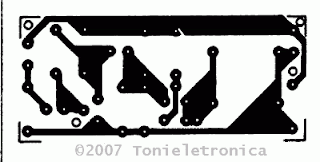
Here's Printed circuit boards and component layout of the
signal amplifierCharacteristic and Specifications technique for
signal amplifier-booster with
BFR90- Answers of Frequency: 40 - 900 MHz
- Gain: 20 dB
- Maximum level of output: 90 µV
- Input-output impedance: 75 ohm
Signal Amplifier Circuit's Parts ListR1 = 82 Kohm
R2 = 270 ohm
R3 = 1,5 Kohm
R4 = 120 ohm
C1,C3 = 100 PF
C2 = 2.2 pF
C4,C5 = 1 nF
D1,D2 = 1N4148 diode
Transistor = BFR90, BFR91, BFR90,
Several = PCB, solder, battery 9V, metallic box, clip to battery, etc.
L1, L2=diameter: 5 mm thread diameter:0,5 mm turns: 8
See more :
Stereo FM Transmitter
 ore rigorous standards, the ARRL encouraged hams to improve their stations. One improved transmitter design was a single tube Hartley oscillator described by Ross Hull in the August 1928 issue of QST. Bruce Howes, W1UJR, covers this design on his web site here.
 ough multiple boxes and peanut butter jars I've lots of possibilities. Now it's a matter of sorting through what I have for the parts that match the original design.


