I write this as asked a few questions about my name on the Elecraft UK builders list.... http://www.elecraft.com/k2_builders.htm
I don't get paid by them to build for anyone and I don't pay them to include me on the list.
Exchange with one amateur from UK and I am building his K1 right now:
> I hope you don't mind me asing... I wonder how much you charge for your services? I am just in the process of buying a K1-4 and unfortunately just do not have the ability to build kits anymore due to a disability just don’t have the feeling in my fingers anymore since an accident last year).
My response:
Don't mind at all.
Yes I do build some things for others including now being asked to build Elecraft kits. Right now shack is insulated (and now heated so maybe less vfo drift!) with power etc. I have an IQPro DDS near completion, a PIC-A-STAR and a 500KHz TX needs finished off. I have just finished a number of softrock SDR builds but I only tend to work on my own things couple hours at a time. I can push these to one side easily and focus on this. If not in a rush I should be able to complete it pretty quickly. One self imposed rule is I would not build for more than one at the same time.
Charges... I have never charged to build anything yet. I work in IT and my normal charge rate is way too much to make this a way of earning a living and as this is a hobby I am happy to help others as many helped me early on :-) If work takes me away from home I suspect will not take with me but we can discuss this if it happens.
I was recommended to offer to build things by Elecraft after some saw my GQRP kit build display last year at Rishworth of BTX-20, PFR-3, MKARS80, HB-1A, numerous SMT Softrock SDR builds, an N2PK VNA and ATS-3 (6 band 100% SMT build and fits in an altoid tin!). Anyway I was asked if I would build for others and as I built a K1 a while back thought why not. I bought the K1 as a part build from a rally, thought it was SSB too initially as miss labeled and I sold it at another rally on a bring and buy stall as my CW wasn't/ still isn't that good and I was not using it. I don't have any contact with who bought it though.
No charge to build but you'd have to buy the kit and send it to me and cover the costs of the kit and postage to me and back. Buying from US if sent direct to me I 100% expect there will be some customs charge of one sort or another. But how about helping with things I'd maybe use to build it:
As this is through hole the irons I'd use are 18W Antex and a temperature controlled iron also from Maplin so suggestions are:
LeadFree Solder 100g N29AR £5.99 or 250g N30AR £9.99
No Clean Flux Disp. N63AA £7.99 Sometimes a flux pen helps but might not even need it as no SMT involved
Tip Tinner Cleaner JG06G £7.99 I like this and not the brillo pad thing GQRP sells but the little tin does appear messy after 25 hours soldering use. I replace these about cnce every 2 months.
Antex Tip Set4 3Pk N15FR £9.99 I have found lead free solder does 'eat' tips so will need one at least
Solderbraid 1mm N47FX £2.69 Small reel is more than sufficient.
I'd not expect I would need to clean the board up after with isoprop alcohol and an old toothbrush but Maplin do it in a hand spray can.
PCB Cleaner 200ml N64AN £3.49
Anyway that is what I'd use to build so pick a couple and add them into the kit you send. Any of the solder, braid, spray or flux left over I send back with the built kit.
Note what Elecraft say about solder if you don't get the Maplin one:
We recommend small-diameter (.02 to .04") rosin-core solder,
similar to Kester type 44. Solder with 2% silver is used by some
builders and will work equally well. If you use a minimum of solder,
there will be no need to clean PC boards. The use of acid-core
solder, water-soluble flux solder, or any corrosive or conductive flux
solvent is likely to damage components and/or PC boards.
If you note the K1 manual... I'd build with a print off and make notes on findings as I build, this would come back to you too. Don't send me a manual unless Elecraft say something new not available from them by PDF.
If a K1-4 that means the K1 and KFL1-4 module manuals.
Just let me know which bands you need.
A guarantee can offer is if I totally mess the build up I'll pay for the components from Elecraft to fix or buy you a new kit.
So hopefully that will answer any questions.
Wednesday, April 25, 2012
Sunday, April 22, 2012
SDR

I saw this and thought was hillarious (grabbed from here http://xkcd.com/730/ and http://xkcd.com/643/)

In addition working a lot with Simon HB9DRV and SDR-RADIO.com building the MOBOKIT V4.3 for him to use.
Thursday, April 19, 2012
Wireless FM Transmitter
This wireless FM transmitter is designed to use an input from another sound source and transmits on the commercial FM band. This low power fm radio transmitter it is actually quite powerful. The first stage is the oscillator, and is tuned with the variable capacitor. Select an unused frequency, and carefully adjust C3 until the background noise stops (you have to disable the FM receiver’s mute circuit to hear this).
When assembling the wireless transmitter circuit, make sure the rotor of C3 is connected to the +9V supply. This ensures that there will be minimal frequency disturbance when the screwdriver touches the adjustment shaft. You can use a small piece of non copper-clad circuit board to make a screwdriver - this will not alter the frequency.

Q1 is a conventional Colpitts oscillator design. The audio signal applied to the base of Q1 causes the frequency to change, as the transistor’s collector current is modulated by the audio. This provides the frequency modulation (FM) that can be received on any standard FM band receiver.
The inductors are 9.5 turns of 1mm diameter enamelled copper wire. They are close wound on a 3mm diameter former, which is removed after the coils are wound. The output is a low power of 100 mW, but for some of you this fm transmitter can delivers the desired power for broadcasting on your street or with a proper antenna you can cover a small neighborhood. If you need a power transmitter use the above menu, you can find transmitters starting with low fm power up to high power fm transmitters.
Source: Low power fm transmitter
Check this out Voice Transmitter
When assembling the wireless transmitter circuit, make sure the rotor of C3 is connected to the +9V supply. This ensures that there will be minimal frequency disturbance when the screwdriver touches the adjustment shaft. You can use a small piece of non copper-clad circuit board to make a screwdriver - this will not alter the frequency.
Q1 is a conventional Colpitts oscillator design. The audio signal applied to the base of Q1 causes the frequency to change, as the transistor’s collector current is modulated by the audio. This provides the frequency modulation (FM) that can be received on any standard FM band receiver.
The inductors are 9.5 turns of 1mm diameter enamelled copper wire. They are close wound on a 3mm diameter former, which is removed after the coils are wound. The output is a low power of 100 mW, but for some of you this fm transmitter can delivers the desired power for broadcasting on your street or with a proper antenna you can cover a small neighborhood. If you need a power transmitter use the above menu, you can find transmitters starting with low fm power up to high power fm transmitters.
Source: Low power fm transmitter
Check this out Voice Transmitter
More TZ-20 Amplifier


With the chassis and front panel drilled, punched and painted this project should start looking more like a kit. Everything is in hand, all I need to do is mount, wire and solder.
I laid out the chassis and front panel so that eventually this amplifier will serve as an upper deck of a 70 watt CW transmitter. My 1934 transmitter will be the lower deck/driver.
My Dissertation: Open Source SCADA System
Just a quick note to say that I've uploaded my dissertation to SourceForge. It is an open source, Java based SCADA package.
SourceForge link is: https://sourceforge.net/projects/ocpscada/
And the wiki link is: http://sourceforge.net/apps/mediawiki/ocpscada/
More details will follow, I'm sick of typing by now - I just spent the day filling my wiki
SourceForge link is: https://sourceforge.net/projects/ocpscada/
And the wiki link is: http://sourceforge.net/apps/mediawiki/ocpscada/
More details will follow, I'm sick of typing by now - I just spent the day filling my wiki
Sunday, April 15, 2012
RF Power Amplifier 80W 2SC2782
 This is a conventional FM RF power amplifier design, using bipolar transistors in a tuned class C circuit. Thanks to the use of two stages, the amplifier can be driven to full power with less than 1 watt driving power, so that a large gain margin results in this FM transmitter.
Bipolar VHF power transistors have a severe affinity for low frequency self- oscillation. To obtain stability in this amplifier, I employed several techniques, such as placing the resonances of base and collector chokes far apart, damping the chokes with resistors, using RC combinations for absorption of unwanted frequencies, using feedtrough capacitors for bypassing on the board, etc. It took some tweaking, but the amplifier ended up unconditionally stable.

The impedance matching network between the two transistors calls for such a low inductance, that it would be impractical to make it with actual wire. So I used a micro stripline etched on the PCB. Also, the power and SWR sensor at the output was made with micro striplines.
This amplifier has a low pass filter at the output, resulting in a signal clean enough to be directly connected to an antenna. The SWR meter was placed before the filter, in order to clean out the harmonics produced by its diodes. In any case, while the signal is clean enough to easily satisfy usual legal and technical requirements, this transmitter should not be used at a multi-transmitter site without further narrowband filtering! This is so because any other strong signals on nearby frequencies would be picked up by the antenna and coupled to the power transistor, which would mix it up with the own signal, creating a wide array of intermodulation products, some of which would be re-radiated! This is a common and very big problem in many multitransmitter sites. In such places, NOT EVEN ONE FM transmitter should be allowed on the air without narrowband filtering! Such filtering is easily accomplished by means of a single tuned cavity, which can be constructed from copper tubing or sheet.
RF Power Amplifier 80W parts overlay without parts identification!

Here is the PCB layout, including the microstrips. The board is 20cm long and is double-sided, with the backside being a continuous groundplane except for two small pads at the driver transistor base and collector. I cut out these pads with a knife, rather than making a whole computer drawing for that!

Source: 80 Watt FM stereo broadcast transmitter
See more: RF TV Modulator - Audio Video RF Modulator - TV Modulator
SDR talk/demos
Done a couple of rally table/stall demos of SDR radios and asked about which ones to get/buy/build... In addition to some notes on software for the softrock SDR radios from Tony Parks KB9YIG I'll document some notes and ad them to the blog shortly.
Loch Erne Rally 11th April 2010 (Enniskillen, Northern Ireland)


Just got back.
Photos of the table showing the SDR demos I ran.
I also managed some /P operation from the rally as MI1KTA/P into a 20m dipole and then on the trip back on two afternoons from the beach near Dublin as EI/M1KTA/P and managed several 2xqrp contacts. Worked qrp DX included RA1CW and 4X4FR.


Friday, April 13, 2012
Springtime - QRPtime
With an early spring here in SE Minnesota I can start thinking about QRP again. One of my favorite local picnic table QRP spots here in Rochester is Essex Park. It has plenty of space, lots of trees with limbs about right for antenna supports and movable picnic tables. Take a look here for a video on my operating from Essex park. On Saturday I worked N1LU, Don in NH, and K1TG, Roger in CT. K1TG was an especially good QSO. We are both active in the AWA and have worked each other using our vintage stations.
This weekend at Essex Park I also worked on a new antenna. My end fed half wave and full wave wire antennas do a fine job but they require at least one well placed tree. I could use a self supporting antenna. Cabellas (and other big box sporting goods stores) sell a 16.5' collapsible crappie (as in fishing) pole. 16.5' is just about right for half of a 20 meter dipole. On Sunday I setup two of these poles to form a V to support a V (not inverted V) dipole. Read more about this antenna here. It appears to work as well as a straight dipole and it is fairly portable....now I need to find a bare nob of a hill to operate from.
This weekend at Essex Park I also worked on a new antenna. My end fed half wave and full wave wire antennas do a fine job but they require at least one well placed tree. I could use a self supporting antenna. Cabellas (and other big box sporting goods stores) sell a 16.5' collapsible crappie (as in fishing) pole. 16.5' is just about right for half of a 20 meter dipole. On Sunday I setup two of these poles to form a V to support a V (not inverted V) dipole. Read more about this antenna here. It appears to work as well as a straight dipole and it is fairly portable....now I need to find a bare nob of a hill to operate from.
Monday, April 9, 2012
Thursday, April 5, 2012
Loch Erne (Enniskillen) Rally 11th April

Just getting the display of kits ready.
Cannot bring the whole shack so in the box will be (everything I have soldered from kits):
The web links are current and provide info on them, some not from vendor.
HB-1A / Direct from BD4RG http://k1hah.net/HB-1A-MK-II.html
PFR-3 / http://www.qrpkits.com/pfr3.html
ATS-3B / KD1JV http://kd1jv.qrpradio.com/ATS3B/ats3b.HTM
MKARS80 & CW Adapter /G6ALU http://www.radio-kits.co.uk/mkars80page.html
BITX20A / http://www.qrpkits.com/bitx20a.html
Softrock -40 (yes the one that started the SDR craze off) / AmQRP & KB9YIG http://www.amqrp.org/kits/softrock40/
FCC-1 & FCC-2 Frequency Counter and DDS / Norcal http://www.norcalqrp.org/fcc1.htm http://www.norcalqrp.org/fcc2mkii.htm
Si570 USB DDS / G0BBL http://www.sdr-kits.net/USB/USB_Description.html
A simple keyer / ??
Tenna Dipper / KD1JV http://www.4sqrp.com/kits/td/td.htm
SLT Tuner / http://www.qrpkits.com/sltplus.html the new version
BLT Tuner / G3RJV but look here http://www.qrpkits.com/blt_plus.html
FUCHS Antenna (OK so this one I built off schematic!) / qrpproject.de
Softrock V6.2 Lite 20m /KB9YIG http://www.wb5rvz.com/sdr/New_SR_Lite/
FDIM2008 11W PA Buildathon - FDIM 2008 Proceedings.
10W PA / W8DIZ http://www.kitsandparts.com/linearamp.php
Digital Dial / http://www.qrpkits.com/freqcounter.html & KD1JV
For the SDR display will have:
Softrock V9.0 With electronic BPF
Softrock Ensemble RXTX
I might have a V6.2 & V6.3 RXTX.
I will have a few KB9YIG unmade kits for sale with me if interested.
Wednesday, April 4, 2012
EnsembleTRX with HB9DRV SDR-Radio Beta
Just finished building and here is a short video of it working.
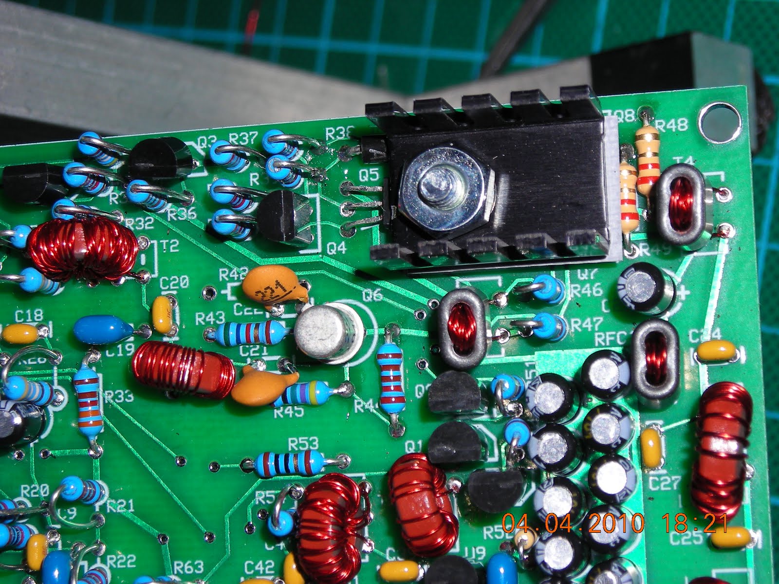
EnsembleTRX PA


The final stage of construction.
I built this for 80m and 40m and T3 and T4 are small and the windings tight.
In both cases the bifilar Secondary(T3) and the bifilar Primary (T4) are wound first with the single wire winding being added last. You may find this a little easier.
Now usually if this were a V6.2 or V6.3 I would have added a drop of heat sink compound to the PA transistors before adding the heatsink but a plastic TO220 washer was included so I used that.
The 2N2222A TO18 heatsink is removed in this photo.
I will run a few quick tests and then clean up the boards.
Until I do as asked for them here are some high resolution pictures of the completed boards.
With no flash:
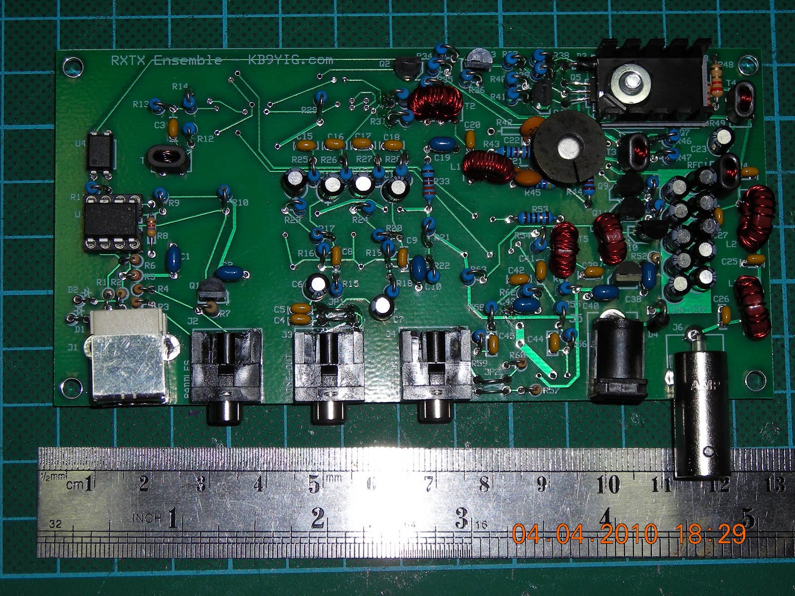
Flash:

Underside:

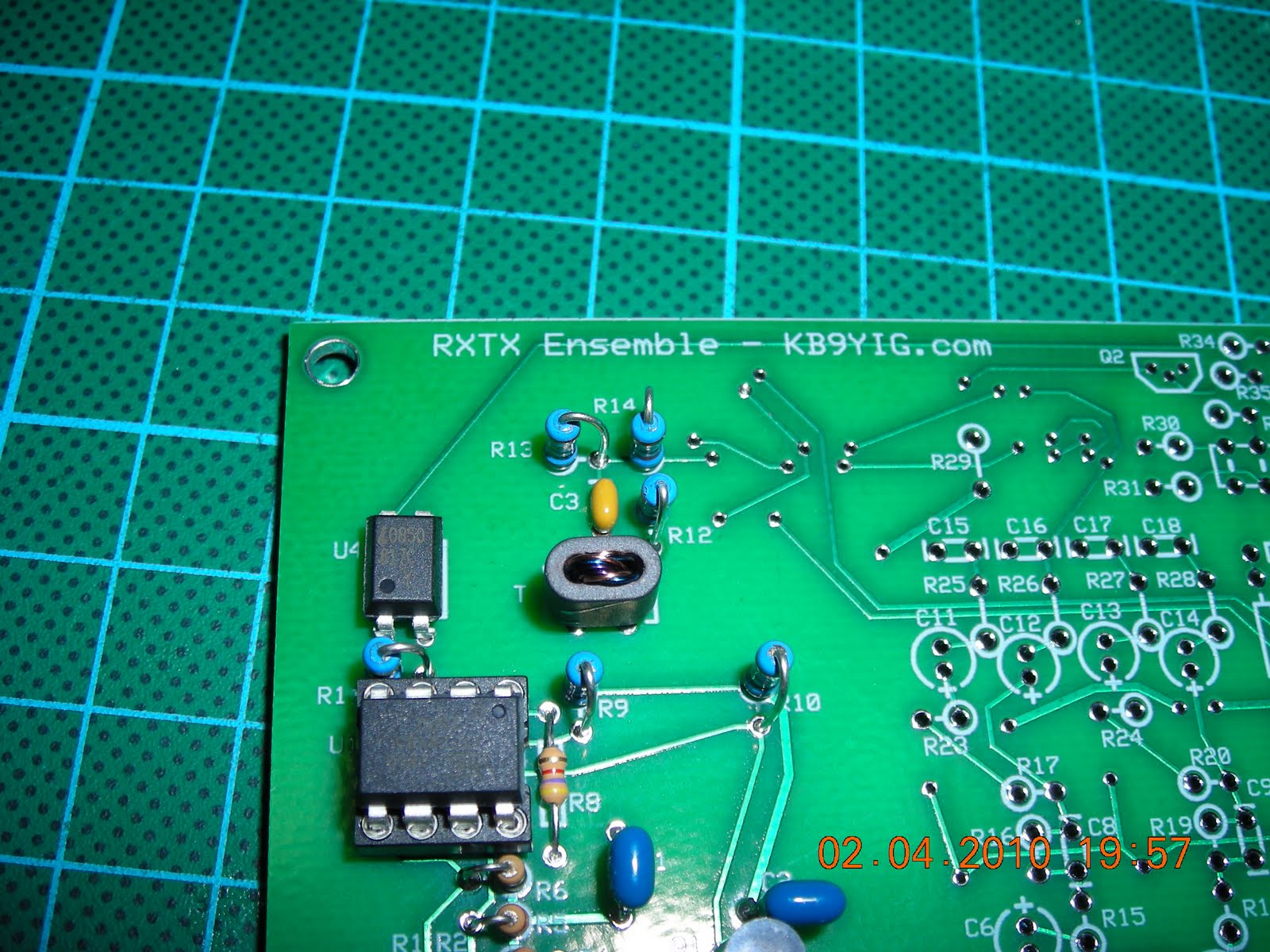
EnsembleTRX TX Mixer (QSE)


This is 1 SMT Ic and 4 SMT C underneath and on top an additional transformer (T2) and inductor (L1), 9 resistors, 3 C and a couple transistors.
I had to substitute in for one of the 220pF caps (C21)


.bmp)


.bmp)
.bmp)


